
The Knowledge Centre
EXPLORE AND LEARN
FAQ video shorts
Frequently asked questions
ELECRTICAL GENERAL
What is electricity?
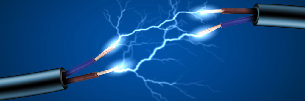
Electricity is a form of energy that results from the flow of charged particles, usually electrons. It is a fundamental aspect of nature and is essential to many of the technologies and devices that we use in our daily lives, such as lighting, heating, cooling, communication, and transportation. In simple terms, electricity can be thought of as a flow of electrons through a conductor, such as a metal wire.
When a voltage is applied across the ends of a conductor, the electrons flow from one end to the other, creating an electrical current. The flow of electrical current can be used to perform work, such as powering a motor or lighting a bulb.
Electricity can be generated in several ways, including through the use of fossil fuels, nuclear energy, hydro power, wind power, and solar power. The generated electricity is then transmitted over long distances to
where it is needed through electrical transmission lines, before being distributed to homes and businesses through electrical distribution networks.
Electricity is also a key component of many natural processes and plays a role in phenomena such as lightning and electrostatic discharge. It is a complex and dynamic field of study, encompassing a wide range
of phenomena, from the behavior of individual electrons to the behavior of large-scale electrical systems.
In summary, electricity is a form of energy that results from the flow of charged particles, usually electrons, and is essential to many of the technologies and devices that we use in our daily lives. It can be generated through a variety of methods and is transmitted and distributed over long distances to where it
is needed.
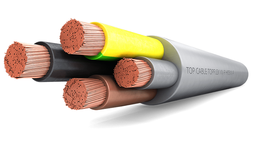
What are electrical cables made of?
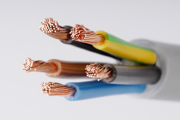
- Electrical cables are typically made of a combination of materials, including conductors, insulation, and outer sheaths or jackets.
- The conductors are usually made of copper or aluminium and are responsible for carrying electrical current. These conductors are typically solid or stranded, depending on the specific application and design requirements.
- The insulation is a material that surrounds the conductor and prevents electrical current from flowing between the conductors. Common materials used for insulation include polyethylene, PVC, rubber, and other high-temperature resistant materials.
- The outer sheaths or jackets provide mechanical protection and prevent the cable from being damaged. These jackets are typically made of materials such as PVC, rubber, or thermoplastic materials.
- In addition to these core components, some cables may also have additional components, such as fillers, shields, or armor, to provide additional protection or performance benefits.
How is electricity carried over long distance and what is the electricity loss?
- Electricity is carried over long distances by using high-voltage transmission lines. High voltage reduces the amount of current needed to transmit a given amount of power, which helps to reduce energy losses due to resistance in the transmission cables.
- The electrical energy loss in transmission cables is due to resistance in the conductors, which causes the cable to heat up and some of the energy to be lost as heat. The resistance of the conductor is proportional to its length and inversely proportional to its cross-sectional area.
- To minimize energy losses, transmission lines are often constructed using conductors with a large crosssectional area and are spaced far apart from each other. The conductors are also often made of materials with a high electrical conductivity, such as copper or aluminum.
- In addition to resistance losses, electrical energy can also be lost due to other factors, such as capacitive and inductive effects in the transmission lines, which cause energy to be stored in the electric and magnetic fields surrounding the cable.
- Overall, while some energy loss is inevitable in electrical transmission, careful design and selection of transmission components can help to minimize these losses and ensure that electricity is delivered efficiently over long distances.
What is Volt and what is Voltage?
A volt (symbol: V) is the unit of electric potential difference or voltage in the International System of Units (SI). It is the electric potential difference between two points in a circuit that will cause a current of one coulomb of charge to flow through a resistance of one ohm.
Voltage is an important concept in electricity and is used to describe theṣ amount of electrical energy that drives the flow of current in a circuit.
It can be thought of as the force that pushes the electric charges through a conductor, such as a wire. The voltage difference between two points in a circuit is often referred to as the “electrical potential difference,” or simply “potential difference”. A higher voltage means that there is more energy available to drive the flow of current in a circuit.
In practice, the voltage in an electrical circuit can be measured using a voltmeter. The voltmeter measures the potential difference between two points in the circuit, which can be used to determine the amount of energy that is available to drive the flow of current. The voltage in a circuit can also be manipulated using components such as resistors, capacitors, and inductors, which can be used to control the flow of current and the distribution of energy in the circuit.
What is an ampere?
Ampacity is the measure of the maximum amount of electric current that a conductor or an electrical circuit can carry without exceeding its temperature rating.
It is expressed in units of amperes (A). The ampacity of a conductor or an electrical circuit is an important factor in determining its safe operating capacity and its ability to perform its intended function without overheating and causing a fire or other safety hazard.
The ampacity of a conductor is determined by several factors, including its size, material, and temperature rating. Larger conductors typically have a higher ampacity because they have a larger cross-sectional area and can dissipate heat more effectively. The temperature rating of a conductor is also important because it sets the maximum operating temperature that the conductor can safely sustain without experiencing an excessive temperature rise that can cause it to overheat and fail.
In practice, the ampacity of an electrical circuit is an important factor in the design and installation of electrical systems. Electrical codes and standards provide ampacity tables that specify the minimum ampacity required for different types and sizes of conductors and applications. These ampacity tables help to ensure that electrical systems are designed and installed in a safe and reliable manner, and that they are able to carry the required amount of current without exceeding their temperature rating.
What is an Ohm?
An ohm (symbol: Ω) is the unit of electrical resistance in the International System of Units (SI). It is defined as the amount of resistance that will cause a current of one ampere to produce a voltage drop of one volt across the resistor.
Resistance is an important concept in electricity and is used to describe the
opposition that a material offers to the flow of electrical current. The resistance of a material depends on its composition, its cross-sectional
area, and its length. Materials that have a high resistance offer more opposition to the flow of current, while materials with a low resistance offer less opposition.
In practice, the resistance of an electrical component or circuit can be measured using an ohmmeter. The ohmmeter measures the amount of resistance in the component or circuit, which can be used to determine.
the amount of energy that is being dissipated as heat. The resistance in a circuit can also be manipulated using components such as resistors, which can be used to control the flow of current and the distribution of energy in the circuit.
In summary, the ohm is an important unit in electrical engineering and is used to describe the opposition that a material offers to the flow of electrical current.
What is capacitance?
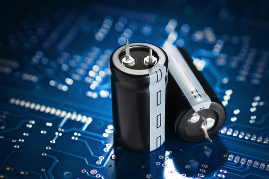
Capacitance is a measure of the ability of a material or a system to store electrical energy in an electric field.
It is the ratio of the electric charge stored on a conductor to the potential difference across it.
Capacitance is an important concept in electrical engineering and is used to describe the behavior of capacitors, which are electrical components used to store and release electrical energy. A capacitor consists of two conductors (usually metal plates) separated by a dielectric material. When a voltage is applied across the conductors, an electric field is created within the dielectric, causing the material to become charged. The amount of charge that can be stored on the conductors is proportional to the capacitance of the system.
Capacitance is expressed in farads (symbol: F), which is a unit of electrical capacitance. One farad is defined as the capacitance of a system where a charge of one coulomb results in a potential difference of one volt.
In practical applications, capacitors are used to store energy temporarily, to smooth out fluctuations in electrical signals, and to filter signals by blocking direct current and passing alternating current. Capacitance can also play a role in the behavior of electrical circuits and can impact the performance of components such as transformers, inductors, and resistors.
What is dielectric strength?
- Dielectric strength is a measure of the electrical insulating properties of a material. It is defined as the maximum electric field strength that a material can withstand without breaking down and becoming conductive.
- Dielectric strength is an important characteristic for materials used in electrical insulation, such as insulators, dielectrics in capacitors, and insulating materials in electrical equipment. It determines the maximum voltage that can be applied to a material without it losing its insulating properties and becoming conductive, which can lead to electrical breakdown and potential safety hazards.
- Dielectric strength is typically expressed in volts per millimeter (V/mm) and is dependent on several factors, including the temperature, humidity, and the presence of contaminants. It is a critical performance parameter for electrical equipment and is usually specified by manufacturers.
- In practice, dielectric strength is used to design and evaluate electrical equipment and systems, as well as to determine the suitability of materials for use as electrical insulators. It is also used as a quality control measure during the manufacturing process to ensure that materials meet the specified requirements.
- In summary, dielectric strength is a measure of the electrical insulating properties of a material and is defined as the maximum electric field strength that a material can withstand without breaking down and becoming conductive. It is an important characteristic for materials used in electrical insulation and is used to design and evaluate electrical equipment and systems.
What is electrical conductivity and conductor resistance?
- Electrical conductivity is a measure of a material’s ability to conduct electrical current. It is defined as the ratio of the current density to the electric field strength in a material. Materials with high electrical conductivity have low electrical resistance and allow electrical current to flow easily, while materials with low electrical conductivity have high electrical resistance and impede the flow of electrical current.
- Conductor resistance is a measure of a material’s opposition to the flow of electrical current. It is defined as the ratio of the voltage across a conductor to the current flowing through it. Conductors with high resistance oppose the flow of electrical current and result in the conversion of electrical energy into heat, while conductors with low resistance allow electrical current to flow easily with minimal loss of energy.
- The electrical conductivity and resistance of a material are important parameters that determine its suitability for use as an electrical conductor. For example, materials with high electrical conductivity, such as copper and aluminum, are commonly used in electrical wiring and electrical equipment due to their low
resistance and ability to conduct electrical current efficiently. - In practice, the electrical conductivity and resistance of a material can be affected by factors such as temperature, pressure, and the presence of impurities. It is also possible to modify the electrical conductivity and resistance of a material by applying electrical fields or by altering its chemical composition. In summary, electrical conductivity is a measure of a material’s ability to conduct electrical current, while conductor resistance is a measure of a material’s opposition to the flow of electrical current. These parameters determine the suitability of a material for use as an electrical conductor and can be influenced by various factors.
What is electromagnetic interference?

Electromagnetic interference (EMI) refers to the unwanted electrical and magnetic signals that can interfere with the normal operation of electrical and electronic devices. These signals can be generated by a wide range of sources, such as electrical motors, fluorescent lights, high-voltage power lines, and radio and television transmitters.
EMI can cause several problems, including the degradation of signal quality,
incorrect operation of electronic devices, and even permanent damage to electronic components. It can also lead to electromagnetic compatibility (EMC) issues, where the normal operation of one electronic device is disrupted by another electronic device operating in close proximity
To minimize the impact of EMI, electronic devices and systems are designed and tested to meet electromagnetic compatibility (EMC) standards, which set limits on the levels of EMI that electronic devices
can emit and be exposed to. This is accomplished through the use of techniques such as shielding, filtering, and grounding, as well as by careful design and layout of electronic circuits.
In some applications, such as in military and aerospace systems, strict EMC requirements must be met to ensure the reliable and safe operation of electronic devices in the presence of high levels of electromagnetic interference.
In summary, electromagnetic interference (EMI) refers to the unwanted electrical and magnetic signals that can interfere with the normal operation of electrical and electronic devices. It can cause a wide range of problems and is mitigated through the use of electromagnetic compatibility (EMC) standards and techniques.
What is fault current?
- Fault current is a high level of electrical current that flows in an electrical circuit when a fault, such as a short circuit or an open circuit, occurs. A fault can cause a significant increase in the current flow in a circuit, which can damage electrical components, create a fire hazard, and even pose a safety risk to people and
equipment nearby. - Fault current is generated when the normal resistance in a circuit is bypassed, allowing a large amount of current to flow. The magnitude of the fault current depends on several factors, including the voltage of the electrical system, the impedance of the circuit, and the type and size of the cables used.
- To protect electrical systems and components from the damaging effects of fault current, electrical engineers design protective devices into the systems, such as circuit breakers, fuses, and ground fault protection. These devices are designed to detect and interrupt the flow of current in the event of a fault, limiting the damage caused by the high level of current.
- In summary, fault current is a high level of electrical current that flows in an electrical circuit when a fault occurs. It can cause significant damage to electrical components and pose a safety risk, and is protected against by the use of protective devices in electrical systems.
What is impedance?
- Impedance is a measure of the opposition to the flow of an alternating current (AC) in an electrical circuit. It is the combination of resistance, which opposes the flow of current due to the conversion of electrical energy into heat, and reactance, which opposes the flow of current due to the storage of energy in an
electric or magnetic field. Impedance is typically measured in ohms and is represented by the letter “Z”. The impedance of an electrical circuit depends on several factors, including the frequency of the AC signal, the inductance and capacitance in the circuit, and the resistance of the circuit components. - In electrical power systems, impedance is an important factor to consider when designing and installing cables and other electrical components. High impedance can cause significant losses in the form of heat, reduce the efficiency of the system, and even cause damage to electrical components. To minimize the impact of impedance, electrical engineers carefully design and select components to ensure that the impedance of the system is within acceptable limits.
- In summary, impedance is a measure of the opposition to the flow of alternating current in an electrical circuit. It is the combination of resistance and reactance, and is typically measured in ohms. Impedance is an important factor to consider in electrical power systems, as high impedance can cause significant losses and damage to components.
What is inductance?
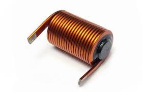
Inductance is a property of an electrical circuit that describes the ability of the circuit to store energy in a magnetic field whenever electric current flow through it. Inductors are the components that exhibit inductance, and they are widely used in electronic circuits for various applications, such as filtering, energy storage, and voltage transformation
The inductance of an electrical circuit is defined as the ratio of the magnetic flux to the current flowing through the circuit. The magnetic flux is a measure of the total magnetic field generated by the current in the circuit, while the current is the flow of electric charge.
Inductance has the important characteristic of opposing any changes in the current flowing through the circuit. This means that, if the current changes quickly, a large voltage will be induced in the circuit, which
will tend to resist the change and keep the current flowing at a constant rate. This property of inductance is known as inductive reactance, and it is a key factor in many electrical and electronic systems, such as power transformers, AC power distribution networks, and electromagnetic devices.
What is the difference between AC and DC?
- AC (Alternating Current) and DC (Direct Current) are two different types of electrical current. The main difference between the two is the direction in which the electrons flow.
- In a direct current, the electrons flow in a single, constant direction. This is the type of current produced by a battery, for example. Direct current is used in applications where a constant voltage is required, such as in electronic devices such as smartphones and computers.
- In an alternating current, the direction of the electron flow changes periodically. This is the type of current that is generated by power plants and is used for electric power transmission over long distances because it can be transmitted more efficiently than direct current. The most common form of alternating current is a sine wave, where the current changes direction sinusoidally. Alternating current is used in a variety of applications, including lighting, heating, and air conditioning.
- In summary, the main difference between AC and DC is the direction of electron flow and the type of applications they are used in. Direct current flows in one direction and is commonly used in electronic devices, while alternating current changes direction and is used for electric power transmission and other applications that require a varying voltage.
What is voltage drop?
Voltage drop is the reduction in voltage that occurs as electrical current flows through a conductor, such as a wire or cable. This reduction in voltage is a result of resistance in the conductor, which causes a portion of the electrical energy to be lost as heat.
Voltage drop can have a significant impact on the performance of electrical systems, particularly in applications where long lengths of cable are used, or where high levels of current flow are required. A high voltage drop can cause a reduction in the amount of power that is available at the end of the cable, which can result in a decrease in the performance of electrical devices, such as motors or lights.
Voltage drop can be calculated using Ohm’s law, which states that the voltage drop across a conductor is proportional to the resistance of the conductor and the current flowing through it.
The formula for voltage drop is:
The formula for voltage drop across a resistor in an electrical circuit is given by Ohm’s law:
V = IR ( Voltage drop = Current x Resistance)
where:
V is the voltage drop (in volts)
I is the current flowing through the resistor (in amperes)
R is the resistance of the resistor (in ohms)
To minimize voltage drop in an electrical system, it is important to use cables with a low resistance and to keep the lengths of cable as short as possible. In addition, it is important to select cables that are suitable for the specific conditions in which they will be used, such as high-temperature or high-voltage applications, to ensure that they have the necessary insulation and protective properties.
By controlling voltage drop, it can be ensured that electrical systems perform optimally and that devices receive the power they need to operate effectively.
CABLE GENERAL
What is the history of electrical cables?
The history of electrical cables dates back to the mid-19th century, when the development of electrical technologies first began to gain momentum. During this period, the first electrical telegraphs were developed, and the need for a means of transmitting electrical signals over long distances became apparent.
The first electrical cables were simple conductors, usually made of copper, that were used to transmit electrical signals over short distances. As the need for longer-distance transmission grew, cables were developed that
consisted of multiple conductors bundled together in a single insulated sheath.
This allowed for the transmission of multiple signals simultaneously, and made it possible to transmit electrical power over greater distances.
In the late 19th century, with the development of the telephone and the first power transmission lines, the need for more advanced electrical cables became apparent. Insulated cables were developed that consisted of a central conductor surrounded by an insulating material, such as rubber, to prevent electrical energy from escaping. This allowed for the safe and efficient transmission of electrical power over long distances.
Over the course of the 20th century, electrical cable technology continued to advance. The introduction of synthetic insulating materials, such as polyethylene and PVC, made it possible to produce lighter and more flexible electrical cables. The development of high-voltage power transmission lines, fiber optic cables, and other advanced cable technologies has also played a significant role in the history of electrical cables.
Today, electrical cables are an essential component of the global electrical infrastructure and are used to
transmit electrical power, data, and signals over long distances. The technology continues to advance, and new
developments, such as superconducting cables and smart grid technologies, promise to play a major role in
shaping the future of electrical cable technology.
How do electrical cables work?
- Electrical cables work by transmitting electrical power from one location to another. They consist of one or more conductors (typically made of copper or aluminum) that are insulated from one another and surrounded by an outer protective sheath.
- When a voltage is applied across the conductors, an electrical current flow through the conductors. The electrical current is the flow of charged particles, such as electrons, that carry energy from one location to another. The size of the electrical current depends on the voltage and the resistance of the conductor.
- In electrical power systems, cables are used to transfer electrical energy from generators to consumers. The electrical energy is transformed into other forms of energy, such as heat, light and motion by the devices that use it. The electrical energy is also transformed into other form
- The insulation around the conductors is important because it prevents electrical current from leaking out of the conductors and potentially causing harm. The protective outer sheath helps to protect the conductors from damage and to prevent electrical interference with other equipment.
- Overall, electrical cables play a critical role in the transmission and distribution of electrical power, enabling the and efficient transfer of energy from generators to consumers.
How are cable sizes selected?
Cable sizes are selected based on several factors such as:
1. Current-carrying capacity: The size of the cable must be sufficient to handle the maximum current that will flow through it without overheating.
2. Voltage drop: The cable must be sized to keep the voltage drop within acceptable limits, particularly for long cable runs.
3. Safety margins: Cable sizes are often selected with a safety margin to account for uncertainties in the actual operating conditions.
4. Industry standards: The cable size must comply with relevant industry standards such as the Bureau of Indian Standards (BIS) or International Electrotechnical Commission (IEC) standards, or British Standards (BS) or specific country standards.
In practice, cable sizing calculations consider all of these factors to ensure that the cable can safely and efficiently transfer electrical power.
What are cable ratings?
Cable ratings refer to the maximum levels of electrical and thermal parameters that a cable is designed to handle without failure or significant degradation of performance. Cable ratings are used to determine the suitability of a cable for a particular application and to ensure that the cable can perform safely and reliably under normal and abnormal conditions.
The most common cable ratings include:
• Voltage rating: The maximum voltage that the cable can safely handle.
• Current rating: The maximum current that the cable can safely carry.
• Temperature rating: The maximum operating temperature that the cable can withstand without degradation.
• Flexibility rating: A measure of the cable’s ability to bend and flex without damage.
• Chemical resistance rating: A measure of the cable’s resistance to chemical degradation.
These are just a few examples of cable ratings. The specific ratings for a cable will depend on the type of cable and the intended application. It is important to choose a cable with appropriate ratings for a given application to ensure safe and reliable operation.
How are cables terminated?
Cables are terminated to connect them to electrical devices or to other cables. Termination refers to the process of attaching the ends of the cable to a connector, such as a terminal block or a plug.
There are several methods for terminating cables, including:
1. Crimping: This method involves using a crimping tool to apply pressure to a metal connector, compressing it onto the cable conductor to make a secure connection.
2. Soldering: This method involves heating the connector and cable to melt a filler metal, creating a permanent bond between the connector and cable.
3. Screw termination: This method involves securing the cable conductor to a terminal block using screws.
How should I select cable glands?
Cable glands are used to secure electrical cables in equipment and protect them from environmental conditions. When selecting cable glands, the following factors should be considered:
1. Cable size: The size of the cable must match the size of the cable gland to ensure a secure and proper fit. Cable glands are available in a range of sizes to accommodate different cable diameters.
2. Cable type: The type of cable must be considered when selecting a cable gland. Different cable types, such as armored or non-armored cable, require different types of cable glands for proper termination.
3. Environmental conditions: The environmental conditions in which the cable gland will be used must be considered. This includes temperature, moisture, chemical exposure, and other factors that could affect the performance of the cable gland. Cable glands are available in materials and finishes that are suitable for different environmental conditions.
4. Safety requirements: Safety requirements, such as explosion proof or flame proof, must be considered when selecting a cable gland. Cable glands are available in different designs to meet different safety requirements and protect personnel and equipment.
5. Equipment type: The type of equipment in which the cable gland will be used must be considered. Different types of equipment may have specific requirements for the size, material, and design of the cable gland.
6. Installation requirements: The installation requirements, such as mounting methods and access, must be considered when selecting a cable gland. Cable glands are available in designs that are suitable for different installation requirements and methods.
It is important to carefully consider these factors and consult with a cable gland specialist or the equipment manufacturer when selecting a cable gland to ensure a secure and proper fit, and to meet the specific requirements of the application.
What are the benefits of using copper vs aluminium conductors?
Copper and aluminum are both commonly used as conductors in electrical applications, and each material has its own advantages and disadvantages.
Benefits of Copper Conductors:
1. Conductivity: Copper has a high conductivity, making it an efficient conductor of electricity. This is particularly important in high-current applications, such as power transmission.
2. Durability: Copper is a durable material that is resistant to corrosion and has a long service life.
3. Jointing: Copper is easy to join using a variety of methods, including soldering, brazing, and crimping, making it an ideal material for use in electrical connections.
4. Recyclability: Copper is a recyclable material, making it an environmentally friendly option for electrical
applications.
Benefits of Aluminum Conductors:
1. Cost-effectiveness: Aluminum is a relatively low-cost material, making aluminum conductors a cost-effective option for many electrical applications.
2. Lightweight: Aluminum is much lighter than copper, making it easier to handle and install.
3. Higher strength-to-weight ratio: Aluminum has a high strength-to-weight ratio, making it an ideal material for use in applications where weight is a critical factor.
4. Corrosion resistance: Aluminum has a natural oxide layer that provides excellent corrosion resistance, making
it suitable for use in harsh environments.
Melting point of Aluminium is 640 deg centigrade. As against that the copper conductor melting point is 1400 deg centigrade.
Overall, the choice between copper and aluminum conductors will depend on the specific requirements of the application, including cost, conductivity, durability, and weight. Copper conductors are generally more expensive than aluminum conductors but offer higher conductivity, durability, and ease of jointing, while aluminum conductors are less expensive and lighter, making them an ideal choice for certain applications.
What are annealed conductors?
- Annealed conductors are conductors that have been heat-treated to reduce their hardness and increase their ductility. This process is called annealing and is performed on materials, such as copper or aluminum, that are used to manufacture electrical conductors. The purpose of annealing is to improve the electrical and mechanical properties of the conductor, making it easier to handle, process, and install.
- Annealing is performed by heating the conductor to a specific temperature for a specified period of time and then cooling it slowly to room temperature. This process changes the structure of the metal at the atomic level, making it softer, more flexible, and less prone to cracking or breaking during installation.
- Annealed conductors are commonly used in electrical power distribution systems, where they are used as or underground electrical cables. They are also used in the manufacturing of wire products, such as electrical wire, grounding wire, and control cable.
- In summary, annealing is a heat-treating process that is used to improve the electrical and mechanical properties of conductors, making them easier to handle and install in electrical power distribution systems and other applications.
What are the benefits of XLPE insulated cables?
XLPE (Cross-Linked Polyethylene) and PVC (Polyvinyl Chloride) are two commonly used materials for electrical cable insulation.
1. XLPE insulation: XLPE is a thermoplastic material that is made by cross-linking polyethylene molecules. This cross-linking process enhances the material’s properties, making it more thermally stable, chemically resistant, and durable compared to unmodified polyethylene. XLPE insulation is commonly used in high voltage and medium-voltage cables, where its high thermal stability and resistance to chemical degradation make it a good choice.
2. PVC insulation: PVC is a commonly used material for low-voltage cable insulation. It is lightweight, flexible, and easy to process, making it an economical and practical choice for many applications. PVC insulation is also flame-retardant, making it suitable for use in applications where fire safety is a concern. However, PVC insulation can become brittle over time and may not be as durable as XLPE insulation in harsh environmental conditions.
Both XLPE and PVC insulation have their own unique set of benefits and drawbacks, and the choice between the two will depend on the specific requirements of the application. Factors such as voltage, temperature, environmental conditions, and cost will all play a role in determining which material is the best choice
XLPE (Cross-linked Polyethylene) insulated cables are widely used in various electrical applications due to several
benefits. The Advantages of XLPE insulated cables over PVC insulated cables are :
Physical & Electrical Properties
1) Cable dimensions get reduced with XLPE insulation as compared to PVC insulated cables
2) As XLPE is lighter than PVC, overall cable weight also reduces, which makes the cable handier.
3) Operating temperature of XLPE insulated cables is 90 °C and that of PVC is 70 °C
4) Short circuit temperature for XLPE insulated cables is 250 °C and that of PVC is 160 °C
5) Emergency temperature rating for XLPE insulated cable is 130 °C and that of PVC is 105 °C
6) Insulation resistance of XLPE insulated cable is 100 times more than PVC insulated cables
7) Volume resistivity of XLPE is 1 x 10^14 ohm-cm & that of PVC is 1 x 10^12 ohm-cm
8) Therefore, current rating of XLPE insulated cable is more compared to PVC insulated cables.
9) In turn XLPE cable carries more power.
10) Better resistance to surge currents.
11) Suitable for installation at sub zero temperatures, whereas standard PVC compound can’t be installed even at low temperature less than 5 °C.
12) Resistant to vibration, impact etc.- no hazard of hot deformation.
Chemical Properties
1) XLPE being thermosetting material, only virgin material is used.
2) XLPE is better resistant to Chemicals and corrosive gases etc. compared to PVC
3) It is also resistant to Hydrocarbons
4) XLPE being lighter than water, it resist water better than PVC.
5) XLPE being cross-linked have better mechanical properties.
6) XLPE is unfilled material more Pure and PVC is filled material, with additives.
| Area mm² | XLPE Insulated Multi-core Cables | PVC Insulated Multi-core Cables | ||||||||
|---|---|---|---|---|---|---|---|---|---|---|
| Voltage Drop | Current rating In Air | Short circuit rating kA(rms) | Voltage Drop | Current Rating In Air | Short circuit rating kA(rms) | |||||
| mV/A/m Al | mV/A/m Cu | Amps Al | Amps Cu | mV/A/m Al | mV/A/m Cu | Amps Al | Amps Cu | |||
| 2.5 | — | 16.37 | — | 36 | 0.36 | — | 15.36 | — | 24 | 0.29 |
| 4 | 16.46 | 10.19 | 30 | 48 | 0.57 | 15.42 | 9.56 | 23 | 30 | 0.46 |
| 6 | 10.24 | 6.81 | 39 | 62 | 0.86 | 9.60 | 6.39 | 30 | 39 | 0.70 |
| 10 | 6.84 | 4.04 | 53 | 84 | 1.43 | 6.41 | 3.80 | 40 | 52 | 1.16 |
| 16 | 4.19 | 2.55 | 84 | 111 | 1.50 | 3.99 | 2.39 | 51 | 66 | 1.32 |
| 25 | 2.67 | 1.61 | 107 | 144 | 2.35 | 2.50 | 1.51 | 70 | 90 | 2.00 |
| 35 | 1.93 | 1.17 | 131 | 178 | 3.01 | 1.81 | 1.10 | 86 | 110 | 2.66 |
| 50 | 1.40 | 0.83 | 158 | 215 | 4.70 | 1.30 | 0.82 | 105 | 135 | 4.06 |
| 70 | 0.99 | 0.61 | 200 | 269 | 6.53 | 0.93 | 0.57 | 130 | 165 | 5.82 |
| 95 | 0.72 | 0.45 | 246 | 333 | 8.93 | 0.68 | 0.42 | 155 | 200 | 7.22 |
| 120 | 0.58 | 0.36 | 280 | 385 | 11.3 | 0.54 | 0.34 | 180 | 230 | 9.10 |
| 150 | 0.48 | 0.30 | 269 | 439 | 14.1 | 0.45 | 0.29 | 205 | 265 | 11.4 |
| 185 | 0.39 | 0.25 | 308 | 507 | 17.4 | 0.37 | 0.25 | 240 | 305 | 14.1 |
| 240 | 0.31 | 0.21 | 364 | 598 | 22.6 | 0.29 | 0.21 | 280 | 355 | 18.4 |
| 300 | 0.26 | 0.17 | 420 | 690 | 28.2 | 0.25 | 0.17 | 320 | 400 | 22.8 |
| 400 | 0.21 | 0.16 | 470 | 785 | 37.6 | 0.21 | 0.16 | 375 | 455 | 30.6 |
| 500 | 0.19 | 0.15 | 533 | 890 | 47.0 | 0.18 | 0.15 | 425 | 516 | 38.0 |
What’s the difference between thermoplastic and thermoset insulation?
The plastic or polymers used in cable insulation are either thermoplastic or thermoset.
Thermoplastic material is softened by heating and can be shaped, with the shape then maintained by cooling. The important characteristic of thermoplastic material is that this process can be repeated with the material resoftened and reshaped over and over again as required. These thermoplastic materials lend themselves to
recycling and reuse.
Thermoset materials are also softened by heating and can be shaped and then cooled to retain a new shape however unlike thermoplastic material, it is only possible to do this once. This is due to a chemical reaction that has taken place during the polymerisation.
Examples of thermoplastic types are PVC (Polyvinyl Chloride) and PE (Polyethylene).
Examples of thermoset types include rubber insulations such as silicone rubbers and EVA (Ethylene-Vinyl Acetate).
PE and PVC may also be cross-linked making them thermosetting types. PVC and XLPE materials which have been cross-linked to make them thermoset materials also have enhanced resistance to temperature, improved dielectric strengths and resistances to certain chemicals.
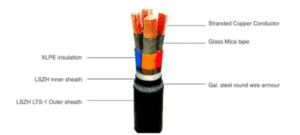
What are the various electrical cable types and what dictates their construction?
There are several types of electrical cables, each with its own unique construction and features to suit specific applications. Some of the most common types of electrical cables include:
1. Power cables: These cables are designed to carry high voltage ranging from 1100 volts (1.1 kV) to 400000 volts (400 kV) and high current and are used in power transmission and distribution systems. They typically consist of a conductor, insulation, armour and a protective outer layer.
2. Control cables: These cables are used to carry low voltage signals in control and instrumentation systems and typically have smaller diameters and lower current-carrying capacity compared to power cables. They may also have additional components such as shielding to prevent electrical interference.
3. Instrumentation cables: These cables are used in process control and industrial automation systems to transmit low-level signals. They may have additional components such as shielding or special insulation materials to improve electrical performance and signal integrity.
4. Fiber optic cables: These cables are used to transmit light signals for data communication and typically consist of a core of optical fibers surrounded by insulation, strength members, and a protective outer layer.
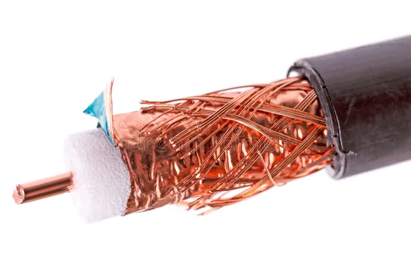
5. Coaxial cables: These cables are used for high-frequency signals, such as in video and broadband communications systems. They consist of a central conductor, insulation, and a braided shield, all surrounded by an outer jacket.
The construction of an electrical cable is determined by several factors, including:
1. Voltage and current-carrying capacity: The voltage and current-carrying capacity of the cable dictate the size and type of conductor and insulation material used.
2. Operating environment: The operating environment, such as temperature, humidity, and exposure to chemicals, can affect the selection of the insulation and protective outer layer.
3. Signal integrity: The signal integrity requirements, such as signal frequency and noise immunity, dictate the type of cable and the use of additional components, such as shielding, for improved performance.
4. Mechanical requirements: The mechanical requirements, such as flexibility, bend radius, and abrasion resistance, dictate the type of cable and the use of additional components, such as strength members, to improve mechanical performance.
In general, the selection of an electrical cable should be based on a careful consideration of the specific requirements of the application, including voltage, current-carrying capacity, operating environment, signal integrity, and mechanical requirements.
What is the operating temperature for electrical cable?
- The operating temperature for electrical cables depends on several factors, including the type of cable, the conditions in which it is used, and the quality of the materials and manufacturing processes used in its production.
- Typically, the operating temperature range for most electrical cables is between -40°C and +90°C. This range covers the majority of environments in which electrical cables are used and allows for a wide margin of safety. However, some specialized cables, such as high temperature or extreme-temperature cables, may have a different operating temperature range to suit specific applications.
- It is important to note that exposure to temperatures outside the specified operating range can shorten the life expectancy of electrical cables and increase the risk of failure. High temperatures can cause the insulation material to degrade, while low temperatures can make the cable more brittle and susceptible to damage.
- When selecting electrical cables, it is important to consider the operating temperature range and to choose cables that are suitable for the specific conditions in which they will be used. This helps to ensure the safety and reliability of electrical systems and reduce the risk of failure and costly repairs.
How is the minimum bending radius determined for cables?
- The minimum bending radius of a cable is determined by its construction and the materials used in its insulation and jacketing. The minimum bending radius is the smallest radius that a cable can be bent without damaging its internal components or impairing its performance.
- In general, the minimum bending radius of a cable is proportional to its overall diameter. The larger the diameter of the cable, the larger the minimum bending radius required to prevent damage.
- The minimum bending radius also depends on the type of cable and the materials used in its construction. For example, cables with soft, flexible insulation or jacketing materials may have a smaller minimum bending radius than cables with stiffer materials.
- In addition, the minimum bending radius of a cable can be influenced by the application in which it will be used.
For example, cables used in tight spaces or in applications where they may be subject to frequent bending may have a smaller minimum bending radius than cables used in more relaxed environments. - To determine the minimum bending radius for a specific cable, manufacturers will typically provide technical specifications or guidelines in their datasheets or installation manuals. These specifications should be followed carefully to ensure that the cable is installed and used in a manner that does not damage its internal components or impair its performance.
What is hydrocarbon resistant cables?
- Hydrocarbons are organic compounds that are made of hydrogen and carbon atoms. They are notably found in crude oil and natural gas.
- Hydrocarbons are either aliphatic or aromatic types, the difference between them is associated with the chemical bonding, with the two types reacting very differently.
- Oil can be particularly damaging to cables. Two different processes can take place, either the plasticizer may migrate from the cable sheathing into the oil causing embrittlement and cracks in the cable sheathing.
- Alternatively, the oil may be absorbed by the cable sheathing and insulation materials causing swelling and softening of the material effecting their mechanical and electrical properties.
- The sheathing material serves as a barrier to moisture ingress and is resistant to hydrocarbons and many other chemicals. It should be noted that, where used, lead has many disadvantages, including environmental concerns, weight, cost and the requirement for large bending radii.
- Today, there are many sheathing materials used as composite or multi-layer sheathing, which may also achieve the same or similar chemical and moisture barriers to Hydrocarbons.
What are longitudinally and Radial water-resistant cables?
- Longitudinally and Radial water-resistant cables are types of electrical cables that are designed to protect against the ingress of water along their length (longitudinal direction) and around their circumference (Radial direction). This protection is important in applications where the cables may be exposed to water, such as in outdoor or underground installations, or in damp or wet environments.
- Longitudinally water-resistant cables are designed with a barrier or protective layer to prevent water from entering along the length of the cable. This is typically achieved through the use of water-blocking materials such as tapes or yarns.
- Radial water-resistant cables are designed with a barrier or protective layer around their circumference to prevent water from entering from the sides. This is typically achieved through the use of water-blocking materials such as metallic tapes or sheaths.
- Both longitudinally and Radial water-resistant cables are important in ensuring the reliability and safety of electrical systems in environments where water may be present.
- Cables designed to be submerged in water or in constant contact with water are usually designed to be both Radial and longitudinally watertight. This doesn’t necessarily mean they’re entirely water-resistant, but if they’re installed in ducts liable to permanent or even intermediate flooding, providing additional protection for sheathing materials that are ultimately permeable can be essential.
- Radial watertight ensures that water can’t penetrate into the cable in the event the sheathing is pierced or damaged. Longitudinally water tight cable is designed with a barrier to the spread of moisture along the cable length.
- Longitudinal water-tightness can be achieved in a number of ways including the use of water-blocking or water swellable tapes and water swellable powders. They are often found either side of a metallic screen.
- Radial water tightness is commonly achieved by a layer of Aluminium backed polyester tape bonded to the underside of the outer sheath.
- Additionally, Class 2 stranded conductors can have water swellable yarns or swellable powders in between the interstices of the stranding to help prevent propagation along the length of the cable in the event of ingress at the point of termination.
What is a Fire Survival cable?
Fire Survival cables are electrical cables that are designed such
• To maintain their functionality and circuit integrity for a specified period of time in the event of a fire.
• Smoke emission is minimum to enable highest visibility for evacuation.
• Reduced emission of harmful toxic gasses to avoid suffocation.
• Enhance heat dissipation through the cable as compared to a regular cable
• Propogation of fire is curbed, stopping it from spreading to other areas.
• Reduces the chances of overheating and Increases the current carrying capacity
Typical Construction of an FS Cable :
In the event of Fire, initially cable has to face Fire alone, which is tested under different temperature & duration as per below mentioned categories;
As per BS 6387
• Resistance to Fire alone
• Cat A 650 °C for 3 hour
• Cat B 750 °C for 3 hour
• Cat C 950 °C for 3 hour
• Cat S 950 °C for 20 Min (Short duration)
Fire is always followed by water sprinkling system to quench the fire; cable has to sustain the same. This
category of test is called as “W” i.e.fire survival cable should retain the circuit integrity with Fire & water
applied together.
In the event of a Fire, it is always accompanied by demolition of building / physical structure, which results in
mechanical shocks. Fire Survival Cable is tested for this type of condition also known as “Mechanical Impact” &
denoted as category “Z” i.e. cable should retain the circuit integrity with Fire & shocks applied together.
Cable passing all the tests under Fire ( C), Water (W) & Impact (Z) conditions, is commonly known as category
“CWZ” as per BS 6387
Categories of ‘Tests under fire conditions’ covered by BS 7846;
• Category F2 Test of cable as per BS 6387 for category “CWZ”
• Category F30 Resistance to Fire with Direct mechanical impact & water assessed in combination for 30 min.
• Category F60 Resistance to Fire with Direct mechanical impact & water assessed in combination for 60 min.
• Category F120 Resistance to Fire with Direct mechanical impact & water assessed in combination for 120min.
• Fire Survival Cables are manufactured using materials that have high fire resistance, low smoke emission, and low toxicity, making them suitable for use in critical applications where fire safety is a concern.
• Fire survival cables are commonly used in emergency lighting systems, fire alarms, and elevator systems, as well as in industrial, commercial, and residential buildings.
• The cable’s insulation and outer layer are designed to prevent the spread of fire and maintain its electrical integrity, allowing the system to continue functioning even in the presence of a fire, which can help in easy evacuation and to minimize the risk of injury and damage.
What is cable laying and lay length?
Cable laying is a term used to describe the way in which a cable is arranged and installed. Cable lay refers to the manner in which the cable is coiled, twisted, or otherwise arranged before it is installed. It is an important factor in determining the performance and longevity of a cable and can impact the cable’s resistance to damage, such as abrasion, crushing, and torsion.
In practice, the type of cable lay that is used will depend on the specific requirements of the application, such as the voltage and current requirements, the environment in which the cable will be installed, and the type of mechanical stress that the cable will be subjected to.
In summary, cable lay refers to the manner in which a cable is arranged and installed and is an important factor in determining the performance and longevity of a cable. The type of cable lay that is used will depend on the specific requirements of the application and the environment in which the cable will be installed.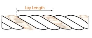
There are several reasons for twisting cables together, including increasing flexibility, strength, concentricity and reducing cross-talk. The cable lay will depend on the reason for the twisting, the diameter of the cables, if there is a required orientation for cores and the number of cores of layers being twisted or laid up.
The cable lay may be left hand lay, known as S stranding or right hand lay, known as Z stranding.
Multiple layers may be wound in alternating directions or the same direction as shown below:

In some configurations the lay is first in the left-hand direction and then in the right-hand direction known as SZ stranding.
What is the life expectancy of electrical cables?
- The life expectancy of electrical cables depends on several factors, including the type of cable, the conditions in which it is used, and the quality of the materials and manufacturing processes used in its production.
- Typically, high-quality electrical cables that are used in indoor, dry, and low-stress environments can last for several decades, with some types of cables having a life expectancy of up to 50 years or more. However, factors such as exposure to high temperatures, corrosive substances, mechanical stress, and UV light can shorten the life expectancy of electrical cables.
- Outdoor electrical cables, or those used in harsh or industrial environments, typically have a shorter life expectancy due to exposure to the elements and other environmental factors. In these cases, the life expectancy of electrical cables can range from 5 to 25 years, depending on the specific conditions and the type of cable used.
- It is important to note that the life expectancy of electrical cables is also influenced by factors such as the quality of the materials and manufacturing processes used, as well as the quality of installation and maintenance. Poorquality cables or those installed improperly may have a significantly shorter life expectancy.
- In general, it is recommended to replace electrical cables that are more than 20 years old, or sooner if they show signs of wear or damage. This helps to ensure the safety and reliability of electrical systems and reduce the risk of failure and costly repairs.
What makes electrical cables suitable for outdoor use?
Electrical cables that are suitable for outdoor use must have certain properties and characteristics to withstand the harsh environmental conditions that they will be exposed to. These properties and characteristics include:
1. Weather resistance: Outdoor electrical cables must be able to withstand exposure to elements such as rain, snow, and extreme temperatures. They must be able to maintain their electrical properties and resist deterioration from exposure to moisture, UV light, and other environmental factors.
2. Mechanical protection: Outdoor electrical cables must be able to withstand physical stress and damage, such as crushing, abrasion, and bending. They must also have a high degree of impact resistance.
3. Chemical resistance: Outdoor electrical cables must be able to resist exposure to chemicals, fuels, and other hazardous substances that may be present in outdoor environments.
4. Flame retardance: Outdoor electrical cables must be able to resist the spread of fire and prevent the cable from igniting in the presence of flames.
5. Insulation: Outdoor electrical cables must have a high level of insulation to protect against electrical shock and to prevent electrical breakdown in the presence of moisture.
6. Durability: Outdoor electrical cables must be able to maintain their electrical properties and mechanical strength over a long period of time, even when exposed to harsh environmental conditions.
Outdoor electrical cables are typically made from materials such cross-linked polyethylene (XLPE) which have a high level of resistance to environmental factors, mechanical stress, and electrical breakdown. They are often designed with additional layers of protection, such steel armour and a UV-resistant outer jacket, to provide additional protection against environmental factors.
When selecting electrical cables for outdoor use, it is important to consider the specific conditions in which the cable will be used and to choose a cable that is suitable for those conditions. This helps to ensure the safety and reliability of electrical systems and reduce the risk of failure and costly repairs.
How do you choose the right electrical cable for a specific application?
Choosing the right electrical cable for a specific application requires consideration of several key factors:
1. Voltage rating: The voltage rating of the cable should be equal to or higher than the maximum voltage that the cable will be subjected to in its intended application.
2. Current carrying capacity: The current carrying capacity of the cable should be sufficient to handle the maximum current that the cable will carry in its intended application.
3. Environmental conditions: The cable should be suitable for the environmental conditions in which it will be installed, including temperature, humidity, exposure to chemicals, and any other factors that could affect its performance.
4. Physical properties: The physical properties of the cable, such as size, weight, and flexibility, should be appropriate for its intended application.
5. Cost: The cost of the cable should be reasonable and affordable for its intended application.
6. Compliance with standards: The cable should comply with relevant industry and regulatory standards, such as safety, electrical, and environmental standards.
7. Manufacturer reputation: The cable should be manufactured by a reputable and experienced manufacturer that has a proven track record of quality and reliability.
It’s important to carefully consider all of these factors when choosing an electrical cable for a specific application, as the wrong choice could lead to issues such as cable failure, reduced performance, and increased costs. In some cases, it may be necessary to consult with an electrical engineer or cable specialist to ensure that the right cable is chosen for a specific application.
What are the main causes of electrical cable failure?
Electrical cable failure can occur for a variety of reasons, including:
1. Overloading: Overloading can cause the cable to heat up, resulting in degradation of the insulation and eventual failure.
2. Mechanical damage: Mechanical damage to the cable, such as bending, crushing, or abrasion, can cause damage to the insulation and conductor, leading to failure.
3. Thermal degradation: High temperatures can cause the insulation material to deteriorate over time, leading to failure.
4. Corrosion: Corrosion of the conductor or connectors can cause failure of the electrical cable.
5. UV exposure: Exposure to UV radiation can cause the insulation material to break down, leading to failure.
6. Chemical exposure: Exposure to chemicals, such as acids, bases, and solvents, can cause the insulation material to break down and lead to failure.
7. Electrical stress: Electrical stress, such as overvoltage or high frequency, can cause the insulation material to deteriorate and lead to failure.
8. Poor installation: Poor installation, such as incorrect termination or incorrect bending radius, can cause mechanical damage and eventual failure.
It is important to regularly inspect electrical cables for signs of damage and replace them if necessary to prevent electrical failure. In addition, it is recommended to follow manufacturer’s guidelines and industry standards for installation, usage, and maintenance to ensure the longevity and reliability of electrical cables
CABLE TECHNICAL
What are electrical cable routine tests?
Electrical cable routine tests are a set of tests performed to assess the quality and safety of electrical cables.
These tests can include:
1. Insulation Resistance Test – to check the insulation resistance of the cable.
2. Continuity Test – to check for any broken or faulty wires in the cable.
3. High Voltage Test – to check the insulation strength of the cable under high voltage.
4. Ageing Test – to check the cable’s ability to withstand ageing.
5. Thermal Test – to check the cable’s ability to withstand high temperatures.
These tests are important to ensure that the cable is safe for use and can perform as expected.
What are electrical cable type tests?
A prototype test – or more commonly type tests in electrical cables is a test performed on a representative sample or a prototype of the cable to verify its performance and characteristics. This test is performed before mass production of the cable to identify and resolve any design or manufacturing issues. The
prototype test is an important step in the development of a new cable and provides valuable information for improving the design and manufacturing process.
This test typically includes many of the same tests as a type test, such as insulation resistance tests, continuity tests, high voltage tests, ageing tests, and impulse tests. The test results from the prototype test are used to make any necessary changes to the cable design and manufacturing process before mass
production begins.
The prototype test is crucial for ensuring that the cable will perform as expected and meet the relevant standards and specifications. It helps to identify any issues or problems before the cable is widely used, which can save time, money, and resources in the long run.
Examples of type tests include:
• Corrosive and acid gas emissions testing
• Mass of zinc coating for galvanized wire armour
• Smoke density testing
• Flame propagation test for multiple cables
• Shrinkage test on insulation
Abrasion test
What are fire performance tests?
Fire performance tests on electric cables assess their behavior when exposed to high temperatures or fire. These tests aim to evaluate the cable’s ability to maintain its insulation properties, prevent the spread of fire, and minimize smoke and toxic gas emission. Some common fire performance tests include:
1. Fire resistance test: This test measures the ability of the cable to maintain its electrical and mechanical integrity during a fire.
2. Smoke emission test: This test measures the amount of smoke produced by the cable during a fire.
3. Toxicity test: This test measures the toxicity of the gases produced by the cable when exposed to fire.
The specific tests and standards used for fire performance testing may vary depending on the type of cable and its intended application.
What is a spark test?
• A spark test is a type of electrical testing that is used to evaluate the quality and safety of electrical insulation or the integrity of the sheath in case of armoured cables.
• The test is performed by applying a high voltage, high frequency impulse to the insulation or the sheath and observing the resulting spark discharge.
• The spark test measures integrity or the pinholes or gaps in the insulation or sheath, which is an indication of its ability to withstand high electrical stress without failing, or pin holes in the same.
• The spark test is used to identify and locate weak spots in the insulation or sheath, which can cause electrical arcing and increase the risk of electrical fires. By identifying these weak spots, the spark test can help to ensure that cable or wire is free from defects.
The test is commonly performed on a variety of electrical equipment and components, including cables, transformers, generators, and other electrical apparatus. The spark test is an important tool for maintaining the safety and reliability of electrical systems and can help to minimize the risk of electrical fires and other
safety hazards.
What is fault current in cables?
- Fault current in cables refers to the high level of electrical current that flows through a cable in the event of a short circuit or other fault condition. When a fault occurs, the normal resistance in the circuit is bypassed, allowing a large amount of current to flow through the cable. This high level of current can cause significant damage to the cable, other electrical components in the system, and even pose a safety hazard to people and equipment nearby.
- The fault current level is dependent on several factors, including the voltage and impedance of the electrical system, the type and size of the cables used, and the location and severity of the fault. To minimize the impact of fault currents, electrical systems are designed to include protective devices such as circuit breakers, fuses, and ground fault protection, which are designed to detect and interrupt the flow of
current in the event of a fault. - In addition, cables used in electrical systems are often specified based on their fault current rating, which is the maximum amount of fault current that the cable is able to safely carry without causing damage.
- When designing electrical systems, it is important to take into account the fault current levels and to ensure that the cables used are able to safely carry the expected levels of current.
- In summary, fault current in cables refers to the high level of electrical current that flows through a cable in the event of a short circuit or other fault condition. The fault current level can cause significant damage to the cable and other electrical components, and pose a safety hazard to people and equipment nearby. To minimize the impact of fault currents, electrical systems are designed to include protective devices and cables are specified based on their fault current rating.
Why is it important to perform Tensile Strength test on Aluminium ?
The tensile strength of aluminum is an important mechanical property that is used to evaluate the material’s ability to resist forces that tend to pull it apart in tension. This property is a measure of the maximum stress that a material can withstand before it fails.
There are several reasons why tensile strength testing is performed on aluminum:
1. Quality control: Tensile strength testing is a common quality control procedure that is used to verify that aluminum products meet the required specifications. The test results provide information about the material’s mechanical properties, which can be used to determine if it is suitable for a particular application.
2. Material selection: Tensile strength testing can be used to compare the mechanical properties of different aluminum alloys, which can help to determine the most suitable material for a particular application.
3. Design optimization: Tensile strength testing can provide valuable information that can be used to optimize the design of aluminum components and structures. For example, the test results can be used to determine the maximum load that a component can withstand, which can help to ensure that
it will perform safely and reliably.
4. Process validation: Tensile strength testing can be used to validate manufacturing processes and to monitor the effects of processing on the material’s mechanical properties.
• In conclusion, tensile strength testing is an important evaluation tool for aluminum, and the test results
can provide valuable information that can be used for quality control, material selection, design
optimization, and process validation.
What is Wrapping Test?
- The wrapping test is a type of electrical cable testing procedure that is used to evaluate the mechanical performance of a cable under external forces. The test is performed by wrapping a cable around a mandrel of a specific diameter and applying a tensile load to the cable.
- The purpose of the wrapping test is to determine the cable’s ability to withstand repeated bending and twisting without failure. The test results provide information about the cable’s flexibility, bend radius, and durability, which are important factors to consider when selecting a cable for a particular application.
- During the wrapping test, the cable is wrapped around the mandrel for a specified number of cycles, and the tensile load is gradually increased to simulate the forces that the cable may be subjected to in service.
- The test is typically performed at room temperature, but it can also be performed at elevated temperatures to simulate the effects of heat on the cable’s performance.
- The wrapping test is an important evaluation tool for electrical cables, and the test results can be used to determine the suitability of a cable for a particular application, to monitor the quality of cable manufacturing processes, and to compare the performance of different cable designs. The specific requirements for the wrapping test are determined by industry standards and guidelines, such as those set by the International Electrotechnical Commission (IEC) and the National Electric Manufacturers Association (NEMA).
What is Tear Resistance test?
- Tear resistance is a measure of a material’s ability to resist tearing or breaking when subjected to a force that is applied along the length of the material. In the context of electrical cables, tear resistance is an important property that is used to evaluate the durability and performance of cable materials, such as
insulation and jacketing. - The tear resistance of a cable material is determined by performing a tear test, which involves applying a tensile force to a sample of the material and measuring the amount of force required to cause the material to tear. The results of the tear test provide information about the material’s strength and toughness, which are important factors to consider when selecting a cable for a particular application.
- Tear resistance is an important property of electrical cables because it affects the cable’s ability to withstand external forces, such as those that may be encountered during installation, operation, or maintenance. Cables that are subjected to repeated bending, twisting, or impact are more likely to fail if the cable material is not tear-resistant.
- In conclusion, tear resistance is a measure of a material’s ability to resist tearing and is an important property of electrical cables that affects the cable’s performance and durability. The specific requirements for tear resistance are determined by industry standards and guidelines, such as those set by the
International Electrotechnical Commission (IEC) and the National Electric Manufacturers Association (NEMA).
Importance of Conductor Resistance Test?
Thermoplastic insulation & sheath exposed to heat are subjected to many types of physical and chemical changes. The severity of exposures, in both time and temperature, determines the extent and type of change that takes place. This test makes an assessment of change in tensile strength and elongation of material on subjecting them to accelerated ageing in air.
Importance of Thermal Ageing in Air
The shrinkage test is a type of test conducted on electrical cables to evaluate their dimensional stability under conditions of temperature change. This test measures the amount of shrinkage that occurs in the cable when it is exposed to a specified temperature for a specified period of time.
The significance of the shrinkage test in electrical cables is that it provides important information about the cable’s ability to maintain its dimensional stability under varying temperature conditions. This information can be used to:
1. Evaluate cable material selection: The shrinkage test can help determine the suitability of a cable material for a particular application by providing information about its dimensional stability under temperature change.
2. Ensure cable quality: The shrinkage test can be used as a quality control tool to ensure that the cable meets specified performance and dimensional stability standards.
3. Predict cable performance: The results of the shrinkage test can be used to predict the cable’s behavior under temperature change, and to estimate its expected dimensional stability over time.
4. Identify potential problems: The shrinkage test can be used to identify potential problems with the cable material or manufacturing process, and to make recommendations for improvements.
Overall, the shrinkage test is an important tool in the evaluation and selection of electrical cable materials, and is widely used to ensure that electrical cables maintain their dimensional stability and performance under varying temperature conditions.
Why is Shrinkage Test conducted in electrical cables?
The plastic or polymers used in cable insulation are either thermoplastic or thermoset.
Thermoplastic material is softened by heating and can be shaped, with the shape then maintained by cooling. The important characteristic of thermoplastic material is that this process can be repeated with the material resoftened and reshaped over and over again as required. These thermoplastic materials lend themselves to
recycling and reuse.
Thermoset materials are also softened by heating and can be shaped and then cooled to retain a new shape however unlike thermoplastic material, it is only possible to do this once. This is due to a chemical reaction that has taken place during the polymerisation.
Examples of thermoplastic types are PVC (Polyvinyl Chloride) and PE (Polyethylene).
Examples of thermoset types include rubber insulations such as silicone rubbers and EVA (Ethylene-Vinyl Acetate).
PE and PVC may also be cross-linked making them thermosetting types. PVC and XLPE materials which have been cross-linked to make them thermoset materials also have enhanced resistance to temperature, improved dielectric strengths and resistances to certain chemicals.
What is Ozone Resistance in electrical cables?
Ozone resistance refers to the ability of an electrical cable material to resist degradation and maintain its performance in environments containing ozone. Ozone is a highly reactive gas that can cause damage to electrical cables and other materials over time, resulting in loss of mechanical and electrical properties.
Ozone resistance is an important property of electrical cable materials, especially in outdoor applications where the cables are exposed to the atmosphere and to the sun’s ultraviolet (UV) radiation, which can cause the formation of ozone. Ozone can cause a variety of problems in electrical cables, including:
1. Material degradation: Ozone can cause oxidation and other forms of chemical degradation in cable materials, reducing their strength and durability.
2. Electrical performance: Ozone can cause electrical properties of the cable, such as its insulation resistance, to deteriorate over time, affecting the cable’s performance.
3. Visual appearance: Ozone can cause discoloration and other forms of visual degradation in cable
materials, reducing their aesthetic appeal.
Therefore, it is important to choose electrical cables that have good ozone resistance for outdoor applications, in order to ensure that the cables maintain their performance and durability over time. In general, cable materials with good ozone resistance are those that are able to resist oxidative degradation and retain their mechanical and electrical properties in ozone-containing environments.
What is Hot Deformation Test?
Hot deformation tests are required in electrical cables to determine the behavior of the cable material under high temperature conditions, which are commonly encountered in many electrical applications. High temperature can cause changes in the material’s mechanical properties, including its strength, toughness, and ductility, which can affect the cable’s performance and service life.
The main reasons for conducting hot deformation tests on electrical cables are:
1. Performance evaluation: Hot deformation tests can be used to evaluate the performance of electrical cables under high temperature conditions, and to determine how the cable’s mechanical properties change with temperature. This information can be used to optimize the cable design and to ensure that the cable meets specified performance requirements.
2. Safety assessment: Hot deformation tests can be used to assess the safety of electrical cables, and to ensure that the cable does not fail under high temperature conditions, which could result in electrical fires or other safety hazards.
3. Materials selection: Hot deformation tests can help determine the suitability of a cable material for a particular application, by providing information about its behavior under high temperature conditions. This information can be used to select the best material for the cable based on its performance and safety characteristics.
4. Quality control: Hot deformation tests can be used to assess the quality of electrical cables, and to ensure that they meet specified standards and requirements.
Overall, hot deformation tests are an important tool in the evaluation and selection of electrical cable materials, and are widely used to ensure that electrical cables are safe, reliable, and perform well under high temperature conditions.
What is Cold Bend test ?
The cold bend test, also known as the cold flexibility test, is a type of mechanical test that is performed on electrical cables to evaluate their behavior under low temperature conditions. The test is designed to measure the cable’s ability to bend and flex without breaking or suffering permanent deformation at low temperatures.
The main importance of the cold bend test in electrical cables is to assess their performance and reliability under cold temperature conditions, which are commonly encountered in many electrical applications, especially in outdoor and extreme temperature environments.
The cold bend test can also be used to:
1. Evaluate cable material selection: The cold bend test can help determine the suitability of a cable material for a particular application by providing information about its behavior under low temperature conditions.
2. Ensure cable quality: The cold bend test can be used as a quality control tool to ensure that the cable meets specified performance and durability standards.
3. Predict cable performance: The results of the cold bend test can be used to predict the long-term performance of the cable under cold temperature conditions, and to estimate its expected service life.
4. Identify potential problems: The cold bend test can be used to identify potential problems with the cable material or manufacturing process, and to make recommendations for improvements.
Overall, the cold bend test is an important tool in the evaluation and selection of electrical cable materials, and is widely used to ensure that electrical cables are safe, reliable, and perform well under cold temperature conditions.
What is Cold Impact test
The cold impact test is a type of mechanical test that is performed on electrical cables to evaluate their behavior under low temperature conditions when subjected to sudden impacts or shocks. The test is designed to measure the cable’s ability to withstand sudden and unexpected impacts without breaking or suffering permanent deformation at low temperatures.
The main importance of the cold impact test in electrical cables is to assess their performance and reliability under cold temperature conditions, especially in outdoor and extreme temperature environments where cables may be subjected to sudden impacts and shocks.
The cold impact test can also be used to:
1. Evaluate cable material selection: The cold impact test can help determine the suitability of a cable material for a particular application by providing information about its behavior under low temperature conditions when subjected to sudden impacts or shocks.
2. Ensure cable quality: The cold impact test can be used as a quality control tool to ensure that the cable meets specified performance and durability standards.
3. Predict cable performance: The results of the cold impact test can be used to predict the longterm performance of the cable under cold temperature conditions, especially when subjected to sudden impacts and shocks, and to estimate its expected service life.
4. Identify potential problems: The cold impact test can be used to identify potential problems with the cable material or manufacturing process, and to make recommendations for improvements.
Overall, the cold impact test is an important tool in the evaluation and selection of electrical cable materials, and is widely used to ensure that electrical cables are safe, reliable, and perform well under cold temperature conditions, especially when subjected to sudden impacts and shocks.
What is Hot Set Test?
The hot set test is a type of hot deformation test that is performed on electrical cables to evaluate their behavior under high temperature conditions. The test is designed to measure the permanent deformation that occurs in the cable when it is subjected to a high temperature for a specified period of time.
The main importance of the hot set test in electrical cables is to assess the cable’s performance and durability under high temperature conditions, which are commonly encountered in many electrical applications. The test results can provide valuable information about the cable’s ability to resist deformation and maintain its electrical performance over time.
The hot set test can also be used to:
1. Evaluate cable material selection: The hot set test can help determine the suitability of a cable material for a particular application by providing information about its behavior under high temperature conditions.
2. Ensure cable quality: The hot set test can be used as a quality control tool to ensure that the cable meets specified performance and durability standards.
3. Predict cable performance: The results of the hot set test can be used to predict the long-term performance of the cable under high temperature conditions, and to estimate its expected service life.
4. Identify potential problems: The hot set test can be used to identify potential problems with the cable material or manufacturing process, and to make recommendations for improvements.
Overall, the hot set test is an important tool in the evaluation and selection of electrical cable materials, and is widely used to ensure that electrical cables are safe, reliable, and perform well under high temperature conditions.
Importance of Carbon Content for Polyethylene
Carbon black is normally used to enhance the weather resistance properties of Polyethylene compound. This test is to determine the quality of carbon black to achieve this result.
Importance of Insulation Resistance (IR)
The Dielectric material in a cable is used to insulate the conductors from one another and from ground as well as to provide mechanical support for the components. For this purpose, it is desirable to have the insulation resistance as high as possible consistent with acceptable mechanical, chemical and heat resisting properties. For this purpose, it is desirable to have the insulation resistance as high as possible consistent with acceptable mechanical, chemical and heat resisting properties.
Why High Voltage test is required?
High voltage testing, also known as high potential (HV) testing, is a type of test that is conducted on electrical equipment, including cables, transformers, generators, and other electrical components, to
verify their ability to withstand high voltage and high electrical stress. High voltage testing is required for several reasons, including:
1. Ensuring electrical safety: High voltage testing is used to verify that electrical equipment can safely operate at high voltages without breaking down, arcing, or creating other electrical hazards. This helps ensure that the equipment operates safely and meets electrical safety standards.
2. Predicting cable performance: High voltage testing can be used to predict the performance of an electrical cable under real-world conditions and determine its expected service life. This information can be used to evaluate the suitability of a cable for a particular application and to ensure that it meets performance and safety standards.
3. Quality control: High voltage testing can be used as a quality control tool to ensure that electrical equipment meets specified performance and safety standards. This helps to ensure that the equipment is reliable and performs as expected.
4. Detecting faults: High voltage testing can be used to detect faults in electrical equipment, such as damaged insulation, loose connections, or other issues that can affect performance and safety.
5. Evaluating new designs: High voltage testing can be used to evaluate the performance of new designs and to identify areas for improvement. This information can be used to develop better and safer electrical equipment.
Overall, high voltage testing is a critical part of the development, evaluation, and quality control of electrical equipment. It helps to ensure that electrical equipment operates safely and meets performance and safety standards, and is an important tool for predicting and verifying cable performance.
Importance of Partial Discharge (P.D)
Partial discharge (PD) is a phenomenon that occurs when a small amount of electrical charge is discharged through the insulation in an electrical system, such as a cable or transformer. PD is an important indicator of the health and condition of electrical equipment, and its measurement and
analysis are critical for ensuring the reliability and safety of electrical systems. The importance of partial discharge can be understood in the following ways:
1. Early detection of faults: Partial discharge is one of the earliest indicators of faults in electrical equipment, such as damaged insulation, cracks, and voids. Early detection of PD allows for the proactive repair or replacement of faulty equipment, reducing the risk of electrical failure and equipment damage.
2. Monitoring cable and equipment health: Partial discharge testing is used to monitor the health of electrical equipment over time, providing valuable information about its condition and performance. This information can be used to predict the expected service life of equipment and to identify areas for improvement.
3. Quality control: Partial discharge testing is used as a quality control tool to ensure that electrical equipment meets specified performance and safety standards. This helps to ensure that equipment is reliable and performs as expected.
4. Evaluating new designs: Partial discharge testing can be used to evaluate the performance of new designs and to identify areas for improvement. This information can be used to develop better and safer electrical equipment.
What is Impulse Test?
An impulse test is a type of electrical test that involves exposing electrical equipment to high-voltage, short-duration electrical impulses. The purpose of an impulse test is to evaluate the performance and stability of electrical equipment, such as transformers, generators, cables, and other electrical components, under high-stress conditions. Impulse tests are typically performed to verify the ability of equipment to withstand electrical transients, such as lightning strikes, power outages, and other electrical events.
Impulse tests are typically performed using an impulse generator, which is capable of producing highvoltage, short-duration electrical impulses. The electrical equipment being tested is connected to the impulse generator, and the impulse generator is used to produce a series of impulses, which are applied
to the equipment. The equipment is then evaluated to determine its performance and stability during and after the impulse test.
The specific type of impulse test performed will depend on the type of electrical equipment being tested and the intended application. Some common types of impulse tests include lightning impulse tests, chopped wave impulse tests, and switching impulse tests.
Overall, impulse testing is a critical part of the development, evaluation, and quality control of electrical equipment. It helps to ensure that equipment is reliable and performs as expected under high-stress conditions, and provides valuable information about the performance and stability of electrical equipment.
Importance of Oxygen Index Test
The oxygen index test is important for evaluating the fire resistance of electrical cables, which are commonly used in various electrical and electronic systems. The test provides information about the minimum concentration of oxygen required to support combustion in the cable insulation material.
The significance of the oxygen index test in electrical cables can be understood in the following ways:
1. Safety evaluation: The oxygen index test helps to evaluate the fire resistance of electrical cables and to determine the level of risk associated with their use in different applications.
2. Compliance with standards: Many electrical cables are subject to specific fire safety standards and regulations. The oxygen index test is used to ensure that the cables and their insulation materials meet these standards and regulations.
3. Product development: The oxygen index test is used in the development of new electrical cables and insulation materials to evaluate their fire resistance and ensure that they meet specific standards and requirements.
4. Quality control: The oxygen index test is used as a quality control tool to ensure that electrical cables and their insulation materials meet specified standards and requirements.
5. Comparison of materials: The oxygen index test can be used to compare different insulation materials and to determine which materials offer the best fire resistance. This information can be used to make informed decisions about the selection of insulation materials for use in electrical cables.
Overall, the oxygen index test is an important tool for evaluating the fire resistance of electrical cables and their insulation materials. It helps to ensure the safety of these products and to ensure that they meet specific standards and regulations.
What is significance of Temperature Index Test?
Oxygen index is most widely used for fire parameter in the assessment of materials. However, the burning significantly influenced by the actual temperature involved. The temperature index helps in the assessment of the material properties under heat and fire. It explores the temperature at which oxygen index of the material becomes 21% i.e. oxygen level preset in the atmosphere.
Why to perform Halogen acid gas determination test of combustion of polymers taken from cables?
For certain locations, the amount of halogen acid gas evolved during burning of cables is very critical since this signifies the extent of corrosion that a compound is capable of causing in an environment. This test is, therefore, carried out on polymeric material components used in cable construction, to determine the amount of halogen acid gas evolved during combustion. This test is not recommended for use where the amount of halogen acid evolved is less than 5 mg / gm. of specimen taken.
What is Thermal Stability test on PVC insulation & Sheath?
The Thermal stability is an accelerated method to determine the rate of degradation of PVC compound with time under influence of temperature. Compounds with high thermal stability can withstand continuous processing temperatures and it is an indication of performance of the cable at normal and elevated temperatures in actual usage.
Understanding Flame Retardant Test for Bunched Cables
The propagation of flame along a bunch of cables depends on a no. of features , such as :
a) Volume of non-metallic material exposed to fire and to any flame which may be produced by the combustion of cables
b) The geometrical configuration of the cables and their relationship to any enclosure.
c) The temperature at which it is possible to ignite gases emitted from the cables
d) The quality of combustible gas released from the cables for a given temperature rise.
e) The volume of air passing through the cable installation
The construction of the cable, e.g. armoured or un-armoured
Why Smoke Density Test is Important?
The assessment of smoke density is an important factor for evaluating the behavior of electric cables under ire conditions. The smoke evolved by one or more burning cables is not necessarily reflected by the testing of the individual components and therefore test method is recommended for cable assemblies.
What is megger test and why is it done on electrical cables?
A megger test is a type of electrical testing used to measure the insulation resistance of electrical cables and equipment. It is also known as an insulation resistance test or mega-ohm test.
The megger test is performed by applying a high voltage direct current (DC) between the conductors of a cable or electrical equipment and measuring the resistance of the insulation. The test measures the ability of the insulation to prevent current flow between the conductors and helps to identify any defects or deterioration in the insulation.
The megger test is done on electrical cables for several reasons:
1. To ensure the cable’s insulation is in good condition and has not been damaged or degraded over time.
2. To verify the quality of the cable’s insulation during the manufacturing process.
3. To diagnose any issues with the cable’s insulation, such as moisture ingress or electrical
discharge, that may affect its performance.
4. To determine the overall health of the cable or electrical equipment and identify any issues that may need to be addressed to ensure safe and reliable operation.
Megger testing is a valuable tool for maintenance and quality control in electrical systems, and helps to ensure the safe and reliable operation of cables and electrical equipment.
CABLE ELECRTICAL
How is current carrying capacity calculated?
The current-carrying capacity of an electrical cable, also known as ampacity, is the maximum amount of electrical current that a cable can carry without overheating. The calculation of current-carrying capacity takes into account several factors, including:
1. Cable size: The cross-sectional area of the conductor affects the cable’s resistance to electrical current. The larger the conductor, the less resistance it will have and the more current it can carry.
2. Cable material: Different materials have different electrical conductivity, which affects the resistance of the conductor. Copper has a higher conductivity than aluminum, for example, so a copper cable can carry more current than an aluminum cable of the same size.
3. Cable temperature: The temperature of the cable affects its resistance to electrical current. As the temperature increases, the resistance of the conductor increases, reducing its ability to carry current.
4. Ambient temperature: The temperature of the surrounding environment affects the temperature of the cable. In hot environments, the cable may need to be sized to handle a lower current to prevent overheating.
5. Cable installation: The installation conditions of the cable, such as the presence of bends or the cable’s proximity to other electrical equipment, can affect its ability to dissipate heat and therefore its ability to carry current.
The current-carrying capacity of a cable is typically specified by the cable manufacturer and may also be limited by industry standards.
In practice, the current-carrying capacity of a cable is calculated by taking into account all of these factors and using mathematical models to determine the cable’s resistance and temperature under different operating conditions
The formula for calculating current carrying capacity is:
I = permissible current rating
ΔΦ = Conductor temperature rise in (°C)
R = Alternating current resistance per unit length of the conductor at maximum operating temperature
(Ω/m)
Wd = dielectric loss per unit length for the insulation surrounding the conductor (W/m)
T1= Thermal resistance per unit length between one conductor and the sheath (K m/W)
T2 = thermal resistance per unit length of the bedding between sheath and the armour (K m/W)
T3 = thermal resistance per unit length of the external Sheath of the cable (Km/W)
T4 = thermal resistance per unit length between the cable surface and the surrounding medium (K m/W)
n = number of load-carrying conductors in the cable (conductors of equal size and carrying the same load)
λ1 = Ratio of losses in the metal sheath to total losses in all conductors in that cable
λ2 = ratio of losses in the armouring to total losses in all conductors in that cable.
How is the Size of cable calculated?
The size of a cable is determined by its cross-sectional area, which is a measure of its capacity to carry electrical current. The cross-sectional area of a cable is calculated based on the number of conductors, their diameter, and the insulation thickness.
The following formula can be used to calculate the cross-sectional area of a single conductor in a cable:
A = π r²
Where: A = Cross-sectional area r = Radius of the conductor π = mathematical constant (approximately equal to 3.1415)
When multiple conductors are used in a cable, their combined cross-sectional area must be taken into account. This can be done by adding up the cross-sectional area of each individual conductor.
Once the cross-sectional area of the conductors has been determined, the appropriate cable size can be selected based on the required current-carrying capacity of the cable. This capacity is determined by the ampacity of the cable, which is a measure of the maximum amount of current that the cable can carry
without overheating.
Ampacity is a function of the cable’s insulation and jacketing materials, as well as its temperature rating. It is important to select a cable with an ampacity that is equal to or greater than the expected current load for the application in order to ensure safe and reliable operation.
The size of a cable can also be influenced by other factors, such as the voltage rating, environmental conditions, and the need for physical protection or shielding. The selection of the appropriate cable size should be based on a careful evaluation of all relevant factors, taking into account the specific requirements of the application and the safety standards that apply.
What are drain wires in electrical cables?
Drain wires are used in “Signal” cables in conjunction with a metallic shield to ensure effective grounding. The drain wire serves to complete an electrical circuit from the shield and carry unwanted electrical noise / static charges etc. to ground away from the circuit.
Generally drain wires are with tin coated Copper. Tin coating is done on copper wires to avoid galvanic corrosion with contact of different metal of screening material.
What is voltage rating?
- The voltage rating of an electrical cable refers to the maximum voltage that can be safely applied to the cable without causing damage or electrical breakdown.The voltage rating is a measure of the insulationstrength of the cable and is expressed in volts (V).
- The voltage rating is a crucial factor in the selection of electrical cables, as it determines the maximum operating voltage of the cable and helps to ensure the safety of the system and its components. In general, electrical cables with higher voltage ratings are more suitable for high-voltage applications, while cables
with lower voltage ratings are more suitable for low-voltage applications. - The voltage rating of a cable is determined by a number of factors, including the type and thickness of the insulation material, the number of conductors, and the size and shape of the cable. In addition, the voltage rating of a cable can be influenced by the temperature and environmental conditions in which it will be
used, as well as the frequency of the voltage being applied. - When selecting electrical cables, it is important to consider the voltage rating and to choose cables that are suitable for the specific conditions in which they will be used. This helps to ensure the safety and reliability of electrical systems and reduce the risk of failure and costly repairs.
What’s the purpose of a screen in MV, HV or EHV cables?
- The purpose of a screen in medium-voltage (MV), high voltage (HV) or extra high voltage (EHV) cables is to provide additional electrical shielding to carry short circuit in case of short circuits. protect the cable from electrical interference, including electromagnetic interference (EMI) and radio frequency interference
(RFI). - A screen is a metallic layer that is wrapped around the inner core of the MV cable, creating a barrier between the electrical conductors and the outside environment. The screen acts as a shield, preventing external electrical signals from penetrating the cable and interfering with the electrical signals being carried by the conductors.
- In addition to providing protection against electrical interference, some type of screens in MV/HV/EHV cables can also provide protection against mechanical damage and electrical breakdown. A screen can help to maintain the electrical and mechanical integrity of the cable, even when it is subjected to mechanical
stress, such as crushing or bending. - There are several different types of screens used in MV/HV/EHV cables, including copper screens, aluminum screens, lead sheaths and tinned copper screens. The choice of screen material depends on the specific requirements of the application and the conditions in which the cable will be used.
- The use of screens is particularly important in applications where high levels of electrical interference are present, such as in industrial and commercial settings. By providing protection against electrical interference, screens help to ensure the reliability and performance of electrical systems and reduce the risk of failure and costly repairs.
Why do certain cables have braiding?
Braided cables are used for several reasons, including:
1. Electromagnetic interference (EMI) and radio frequency interference (RFI) protection: Braided cables can provide additional shielding against electromagnetic and radio frequency interference, helping to prevent electrical signals from penetrating the cable and interfering with the signals being carried by the conductors.
2. Mechanical protection: Braided cables can provide additional protection against physical stress and damage, such as crushing, abrasion, and bending. The braided layer can help to distribute mechanical stress more evenly and prevent damage to the cable’s inner components.
3. Aesthetics: Braided cables can have a sleek and attractive appearance, making them suitable for use in applications where appearance is important, such as in consumer electronics.
4. Durability: Braided cables can be more durable than non-braided cables, as the braided layer provides an extra layer of protection against wear and tear, making them suitable for use in applications where the cable will be subjected to frequent movement or handling.
5. Flexibility: Braided cables can be more flexible than non-braided cables, making them easier to install and handle. This makes them suitable for use in applications where the cable needs to be bent or routed through tight spaces.
Braided cables are often used in applications where electrical interference, mechanical stress, and durability are concerns. The braided layer provides additional protection against these factors, helping to ensure the reliability and performance of electrical systems and reduce the risk of failure and costly repairs.
The material used for the braided layer can vary, depending on the specific requirements of the application. Common materials include copper, aluminum, and tinned copper. The choice of material depends on the desired level of protection, the cost of the cable, and other factors such as flexibility and application.
What is arching and sparking in electrical cables?
- Arcing and sparking in electrical cables refer to the phenomenon of electrical discharge or current flow through the air between two conductors, rather than through the normal path of a cable.
- Arcing occurs when the electrical voltage across two conductors becomes high enough to ionize the air between them, creating a plasma channel that conducts electricity. This ionized air acts as an electrical conductor, allowing current to flow between the conductors, producing an arc.
- Sparking occurs when an electrical discharge or spark is created, typically as a result of an electrical breakdown in a cable or circuit. The spark creates a high-intensity luminous discharge, and can be accompanied by the production of heat, sound, and electromagnetic radiation.
- Both arcing and sparking can cause damage to electrical equipment, pose a fire risk, and create hazards for personnel in the vicinity. They can be caused by a variety of factors, including poor cable
- installations, faults in electrical systems, and high voltage transients. To minimize the risk of arcing and sparking, it is important to follow proper installation and maintenance procedures, and to use cables that are designed to meet relevant safety standards.
What is the difference between Class 1, Class 2, Class 5 and Class 6 conductors?
- Solid conductors are electrical wires that are made of a single, solid piece of metal. They are commonly made of copper or aluminum, and are used in applications where space is limited, such as in small electronic devices and circuit boards.
- Stranded conductors are electrical wires that are made of many small, individual wires that are twisted together. Stranded conductors are more flexible than solid conductors, which makes them ideal for use in applications where the wire needs to bend and flex, such as in automotive wiring and cable assemblies.
- Flexible conductors are electrical wires that are designed to be highly flexible and able to bend and move in a variety of directions. These conductors are often used in applications where the wire needs to be able to move freely, such as in robotics and automation systems, as well as in applications where the wire needs to be able to fit into tight spaces.
- The choice between solid, stranded and flexible conductors depends on the specific requirements of the application and the electrical and mechanical characteristics of the wire. Factors such as currentcarrying capacity, resistance, and flexibility are important to consider when selecting the right type of
conductor for a given application.
CABLE HANDLING
How should electrical cable drums be handled / shipped?
Electrical cable drums should be handled and shipped with care to ensure their safe and proper transport.
The following are some general guidelines for handling and shipping cable drums:
1. Lifting and moving: Cable drums should be lifted and moved using proper equipment, such as a forklift or drum truck to prevent injury to personnel or damage to the cable. When lifting or moving cable drums, it is important to maintain a stable and secure grip to prevent slippage or tipping.
2. Securing for transport: Cable drums should be secured for transport to prevent movement or damage during transit. This can be done by using straps or restraints to hold the drums in place, or by securing them in a container or trailer.
3. Storing: Cable drums should be stored on a dry hard surface, protected area to prevent moisture damage or exposure to harmful environmental conditions. They should be stacked vertically and stored in a secure location to prevent accidental falling or tipping.
4. Loading and unloading: Cable drums should be loaded and unloaded carefully to prevent damage to the cable or injury to personnel. When loading or unloading cable drums, it is important to use proper equipment, such as a ramp or crane, and to follow proper lifting procedures.
5. Shipping: When shipping cable drums, it is important to properly mark and label the packages to ensure that they are handled and transported properly. The packages should be marked with the proper shipping codes, such as “fragile” or “handle with care,” and labeled with the destination and contact information.
It is important to follow these guidelines and any additional safety and handling instructions provided by the manufacturer to ensure the safe and proper handling and transport of cable drums. Failing to follow these guidelines could result in damage to the cable, injury to personnel, or other hazards.
How should electrical cable drums be stored?
Electrical cable drums should be stored in a dry, protected area to prevent moisture damage or exposure to harmful environmental conditions. The following are some general guidelines for storing cable drums:
1. Vertical storage: Cable drums should be stacked vertically to prevent accidental falling or tipping. This will also allow for efficient use of space and easy access to the cable.

2. Dry storage: Cable drums should be stored in a dry area to prevent moisture damage to the cable. Moisture can cause corrosion, electrical discharge, and other hazards that can damage the cable and impair its performance.
3. Protected storage: Cable drums should be stored in a protected area to prevent exposure to harmful environmental conditions, such as heat, sunlight, chemicals, or physical damage. This will help to ensure the longevity and reliability of the cable.
4. Secure storage: Cable drums should be stored in a secure location to prevent unauthorized access or theft. This is particularly important for high-value or sensitive cables that are used in critical applications.
Efficient storage: Cable drums should be stored in an efficient manner to allow for easy access and organization. This can be done by labeling the drums and arranging them in an orderly manner, or by using storage racks or shelving systems. During storage, the drum should be rolled to an angle of 90°
once every three months.

It is important to follow these guidelines and any additional storage instructions provided to ensure the safe and proper storage of cable drums. Failing to follow these guidelines could result in damage to the cable, or other hazards.
The appropriate storage of cable drums and the electrical cable it contains will depend on both the type of drum and whether or not the cable itself is designed for indoor or outdoor use. The following points should
be noted:
• Cable drums should be stored on firm and well-drained ground.
• Cable should be covered from direct sunlight.
• Protective lagging or covering should be used to protect against UV and weathering effects.
• Any cable stored outdoors should be sealed to protect from water ingress.
• Cables should be protected from mechanical damage.
• Drums should be stored on their edges and never on the flanges.
Drums should be secured and prevented from rolling into one another, causing damage due to
misalignment.
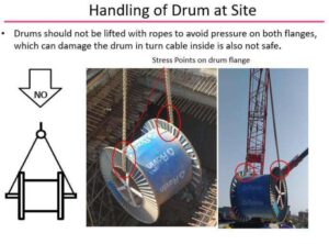
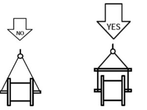
How to handle cable drums?
Cable drums are used to store and transport electrical cables, and it is important to handle them properly to prevent damage to the cable, injury to personnel, or other hazards.
The following are some general guidelines for handling cable drums
1.Lifting and transporting: Cable drums should be lifted and transported using proper equipment, such as a forklift, crane, or hand truck. Lifting cables by hand can cause injury or damage to the cable.
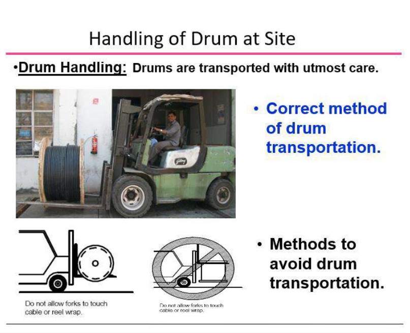

2.Unreeling: Cable should be unreeled from the drum slowly and evenly to prevent kinking, twisting, or damaging the cable. Cable drums should be rotated as the cable is unreeled to ensure even distribution of cable tension.
1. Storing: Cable drums should be stored vertically in a dry, protected area to prevent moisture damage or exposure to harmful environmental conditions. Cable drums should be stacked in an orderly manner to prevent accidental falling or tipping.
2. Safety equipment: Personnel handling cable drums should wear proper safety equipment, such as gloves, eye protection, and hard hats, to protect against potential hazards, such as cuts or falling objects.
It is important to follow these guidelines and any additional handling instructions provided to ensure the safe and proper handling of cable drums.
What is bird caging in cables?
Bird caging is a term used to describe a type of damage that can occur in electrical cables. It is a term used to describe the phenomenon where the armour wires or strips inside the cable are pushed or pulled out of their original position and form a cage-like structure around the central conductor.
Bird caging can occur as a result of excessive bending or twisting of the cable, or laying the drum on its flanges and unwinding the cable, or opening the cable in the opposite or wrong direction of the arrow provided on the drum. This can cause the individual wires or strips of the armour to become dislodged and bulge out. This can result in a bulging or even tearing of the outer sheath. of the cable, which can result in damage to the cable, can also increase the resistance and reduce the ampacity of the cable.
Bird caging can also increase the risk of cable failure by increasing the stress on the individual strands of the cable, which can cause them to break or become damaged. This can result in a loss of electrical continuity, which can cause the cable to fail and disrupt the electrical system.
In practice, bird caging can be prevented by using cables that are designed to withstand the mechanical stress of bending and twisting.
In summary, bird caging is a type of damage that can occur in electrical cables and is caused by wrong laying methods, wrong unwinding of the cable. Or excessive bending or twisting of the cable, which can cause the armour and/or conductor to become dislodged and form a cage-like structure.
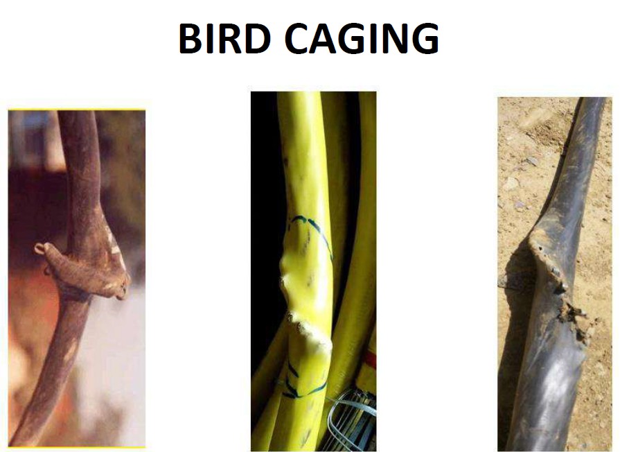
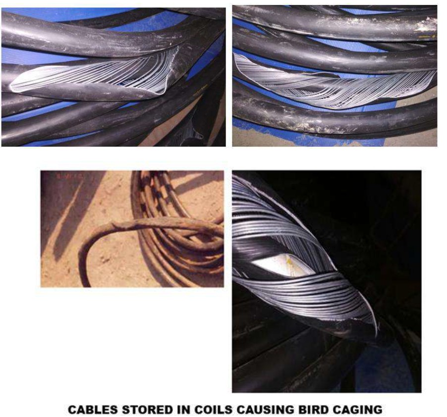
A COMPARISON POLYPROPYLENE (PP) V/S PVC FILLERS
Filters and its Function
Filter And its function
- It is integral Part of 3 crore HT-cable
- Fillers are used to fill the interstitial gaps in the laid up assembly, which gives proper circulatery and better look.
- It helps cable for smooth running by,
- Absorbs mechanimechanical stresses during overloading.
- Helps to retain physical contact between Copper tapes.
Characteristics Of Filters
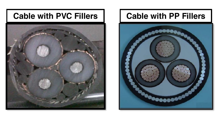
Why PVC Fillers Are Still Used
Why PVC fillers are still used ?
- PVC can be re-processed
- It can extruded as per desired shape i.e. Sector,circular.
- Incapability to use other better filler material.
- Availability of PVC from various processes
- Lack of awareness of new technology and developments.
Limitations Of PVC
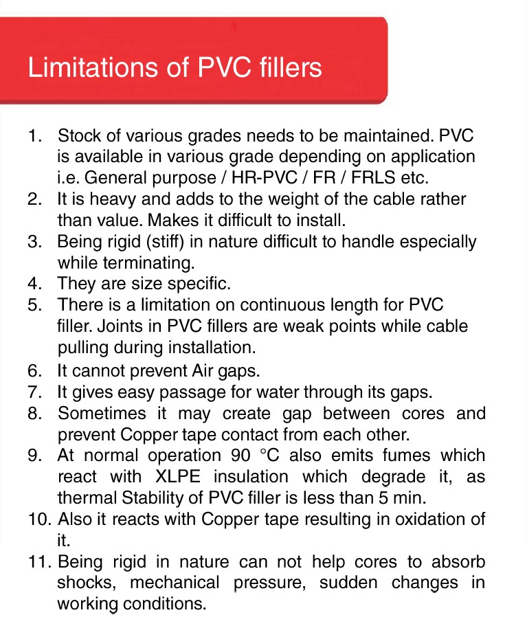
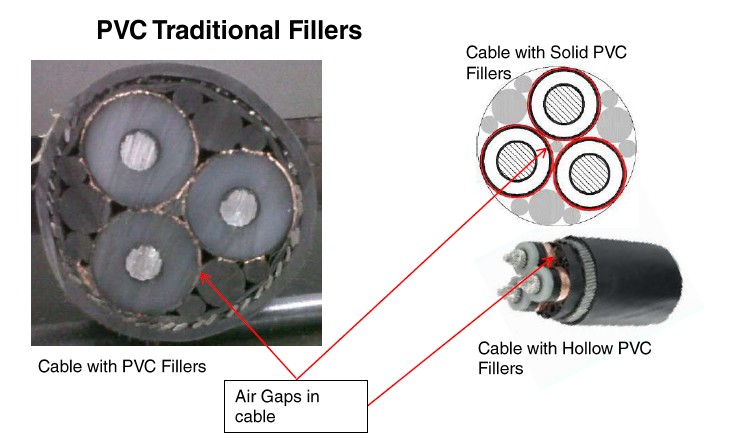
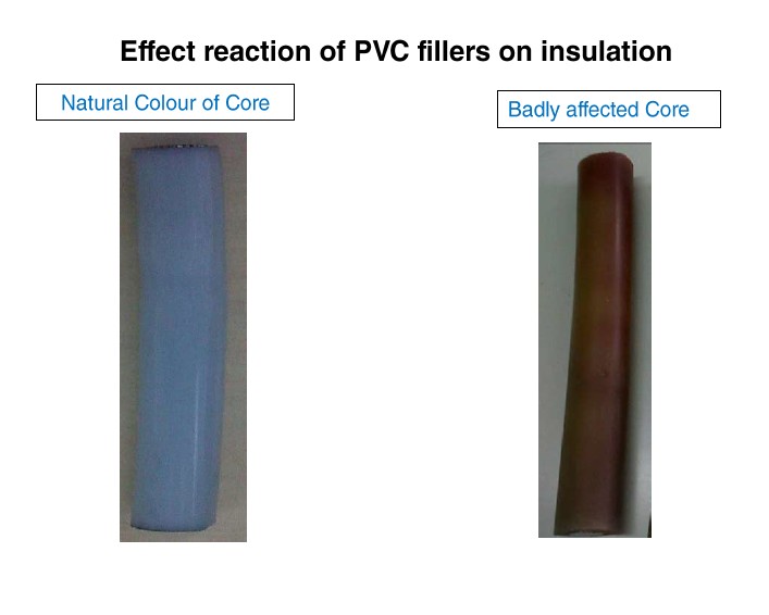
Advantages With PP Fillers
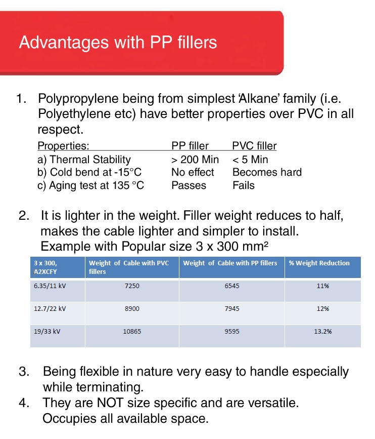

PREVENTION OF FIRES AND ADOPTION
Filters and its Function
• Fire hazards in India have been a common cause of accidents in both residential and commercial sectors. The damages caused by fire accidents have long-standing consequences not only in personal assets but their loved ones and their own lives at times. As a country, India has been witness to fire hazards of various magnitudes.
• Most of these fire incidents are caused due to lack of Safety equipment and training to arrest the Fire in time. In 2021, India sadly recorded 1.6 million fire accidents, with 27,027 innocent lives lost.
• Indian commercial and residential spaces are subjected to several fire hazards and incidents due to a lack of awareness, building layout, and the right instruments. Though it remains one of the most preventable mishaps Fire results in the loss of life and property. While the decline in fire-related
fatalities and injuries is promising, the significantly higher proportion of deaths relative to injuries is concerning. This could indicate the severity & nature of the fire accidents resulting in higher mortality.
• Many commercial outlets such as restaurants, clubs, cafes and other recreational places share common electrical supplies causing massive fire which begins as one small flash which acts as the origin which turns into a massive blazing ball of Fire
• Inadequate healthcare facilities add to fire deaths
• Earlier, women made up for 80% of the fire victims in Mumbai, but now we have started seeing more senior citizens and children in burn wards,” divulged Dr S Keswani of Airoli Burns Centre in Navi Mumbai. This “epidemiological shift” is mainly due to societal changes such as increased longevity and financial independence among women. “Women have jobs, meaning children are either taken care of by elderly at home or at a creche,” he said. The study identified gender violence as a cause for the high death rate in India; it also cited a study from Karnataka that showed synthetic saris worn by women was a cause.
Inadequate healthcare facilities in India add to deaths due to fires. “Burns management needs manpower. Six people are needed each time a burns patient has his or her bandages changed. But our public hospitals, where most victims go for treatment, have poor doctor/nurse-patient ratio,’’ added Dr Keswani. Fire Hazards
Electrical Fires
Without a doubt, this is the most common cause of Fire at workplaces. Whether due to some electrical equipment malfunctioning. Or faulty wiring. Electricity is the most common source of ignition for major fires. The cause may be defective wiring, overloaded sockets or plugs. Using old or malfunctioning equipment causes
overloading and leads to sparks that start a fire on combustible materials. To avoid such problems with electrical fires, you must establish an electrical safety program. A familiarization programme must be carried out with the employees. This way the employees will learn how to be safe and operate safely. It must be made a mandatory practice to use tools, equipment and other goods properly. Extension cords must be inspected before use. If found faulty, removed from service and properly tagged. Damage or inadequate maintenance causes machinery to deteriorate, resulting in unsafe conditions. Do note, the Directors of the company operating that workplace are legally responsible for ensuring that all equipment works and functions correctly, and this includes electrical machinery.
CABLE CONDUCTOR AND OVERVIEW
Filters and its Function
Types Of Conductor

STRANDED V/S SOLID
V/S FLEXIBLE
WHAT DO TESTS SAY?

TORSION TEST
Why torsion test?
• Cables are usually handled by technically untrained workers at the site
• Resulting in rough handling
• Which causes twisting of conductor
• Load is applied on the conductor while handling the cable during Pulling & Termination
What is Torsion Test?
• Simulating the worst handling conditions
• One end of the conductor is fixed, while the other end is turned to twist the conductor
Test:
– To determine the no. of turns taken by a conductor to break completely
– Resembling rough handling and bending conditions while winding, laying and bending
Torsion Test on Solid Conductor

Torsion Test on Stranded Conductor
Results
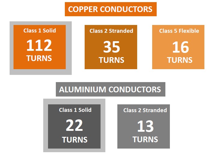
Leading to conclusion

TENSILE STRENGTH & ELONGATION TEST
Why Tensile Strength & Elongation Test?
• Cables are usually handled roughly during pulling & installation
• Stretching of the conductor can cause conductor to break
• And loose its conductivity
What Tensile Strength & Elongation Test?
• Simulating the worst handling conditions
• One end of the conductor is fixed, while the other end is stretched elongate the conductor
Test:
– To determine the length (N/mm2) maintained by a conductor before breaking completely
– Resembling rough handling and bending conditions while winding, laying and bending
Test on Solid Conductor
Results

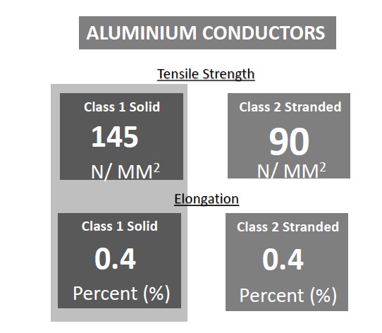
PERFORMANCE IN PRESENCE OF WATER
TEST IN PRESENCE OF WATER (ALUMINIUM CONDUCTOR)
Immersion in water to determine the effect of water on conductor’s properties.
Test after water penetration
Mechanical properties – Aluminum Conductor

Test in Presence of water (Aluminium Conductor)
• Conductor immersed under water for 21 Days at 50 °C
– Immersion in water to determine the effect of water on conductor’s properties.
• Electrical
• Mechanical
Test after water penetration
Mechanical properties – Aluminum Conductor
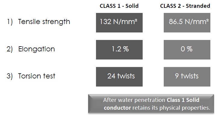
Test after water penetration
Electrical properties – Aluminum Conductor
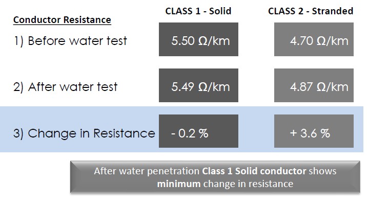
Observations:

STRANDED V/S SOLID A COMPARISON
How do they fare?

CONDUCTOR CONSTRUCTION
CONSTRUCTION OF SOLID V/S 7 STRAND CONDUCTORS

CLASS 2 STRANDED CONDUCTOR BURSTING MYTHS
#1 FLEXIBLE : Easy to handle & bend
The torsion test proves that individual strands are more likely to break on twisting and turning of conductor while handling
#1 FLEXIBLE : Easy to handle & bend
In reality, the individual strands are difficult to bunch for proper termination and hence require a lug to put them in place. Can cause loss of conductivity even if a single strand breaks
#1 FLEXIBLE : Easy to handle & bend
The empty spaces left between the individual strands result in uneven insulation:
– Reducing the di-electric strength
– Causing capacitance
– Even if a single strand breaks:
– The conductor loses its conductivity by 14%
– Loose strands make it susceptible to arching/ sparking
– Leading to creating of hot spots
– Resulting in fires
FACTS ABOUT CLASS 1 SOLID CONDUCTOR
• High di-electric strength
• High tensile strength
• Tough & durable
• Withstands pressure during handling – laying, pulling & Installation
• Protection against corrosion
• Safe
• Cost effective
CONDUCTOR FORMATION WITH GEOMETRICAL CONSTRUCTION

CONDUCTOR – THE CABLE HEART
NO. OF WIRES ACCOMODATED N FIRST
LAYER = 6
d ”=PITCH CIRCULAR DIAMETER
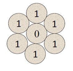
FOR SECOND LAYER = 4X2.20mm
=8.80mm
NO. OF WIRES IN FIRST LAYER = d”X3.14/d
= 8.80X3.14/2.20 = 12WIRE
THAT IS WHY 70 SQ.MM.=19 /2.20 [1+6+12]
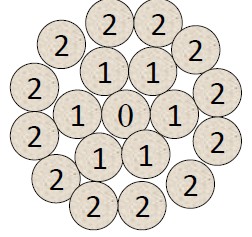
CONDUCTOR – THE CABLE HEART
Of course even with proper number of wires , if the compaction is not proper, it can lead to air gaps, which increase conductor resistance.
Bad Design of Conductor Can Cause 3% to 9% Transmission loss, Failure due to Sharp Edges.
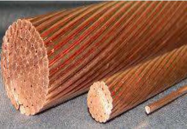
To Summarize
• Smallest area for a given cross section.
• Simple to terminate; no need of Additional Lug. (Cost effective).
• Removing of insulation from conductor is easier. (Time saving & ease of work)
• No snapping of wires due to cable pulling.
• Better elongation allows more pulling force.
• By default a water tight material.

EHV CABLES LAYING & INSTALLATION TECHNIQUES
EHV CABLES LAYING & INSTALLATION TECHNIQUES
INSTALLATION OF EHV CABLES
• Introduction.
• Installation Conditions.
• Data of Accessories: Terminations & Joints.
• Drum Lengths of Cable.
• Methods of Laying.
• Clearances.
• Pre-Commissioning Tests.
INTRODUCTION
• Reliability of Power Cables & Accessories.
• Quality:
a) Raw Materials.
b) Manufacturing Process.
c) Transportation.
d) Laying.
• Laying of Cables
• Jointers – Workmanship.
• Service Conditions.
INSTALLATION CONDITIONS
• Methods of Laying.
• Installation Details.
• Thermal Resistivity of Soil.
• Soil Temperature.
• Dimensions of Trench.
• Details of Cable already in Trench: nType, Number, Conductor Size & Loads.
• Challenges Faced.
• Mechanical Stress & Vibrations.
• Grouping of Cables.
DATA OF CABLE ACCESSORIES
• Terminations:
Number of Terminations
Type : Outdoor / Indoor.
Pollution Level & Humidity Level.
Desired Type : Voltage Level.
Space Available.
• Joints:
Type of Joint.
Voltage Level.
Soil Conditions : Sub-soil Water Level.
Whether the Soil will Sink & Vibrate.
Type & Size of Existing Cables.
CABLE DRUM LENGTHS
• Length as per Initial Route Survey.
• Weight of Drum & Dimensions : Heavier Cables – Heavy Duty Metal Drums.
• Transportation.
• Un- Loading Facility & Infrastructure.
• Site / Stores
TYPE OF MOUNTING
• Vertical Mounting : Self Supporting Type.
• Design in Consultation with Utility & Cable Manufacturer.
• Minimum Permissible Bending Radii – 20 x D
• At Joints & Terminations : Individual Cores ≥ 15 x Dia. Over Insulation.
CONVENTIONAL METHODS OF CABLE LAYING AND INSTALLATIONS
• Laying Direct in Ground.
• Drawing in Ducts.
• Laying on Racks in Air.
• Laying on Racks Inside a Cable Tunnel.
• Laying Along Buildings or Structures.
LAYING DIRECT IN GROUND
• Digging a Trench in Ground.
• Bedding Minimum 75mm.
• Laying on the Sand / Suitable Bedding.
• Covering with Minimum 75mm.
• Protection : Tiles / Bricks / Slabs.
Storage shall be on the firm floor with proper supports
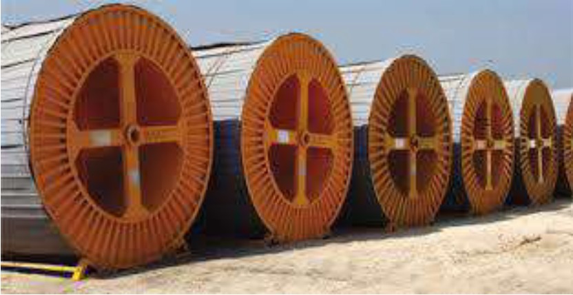
Cables laid in ground
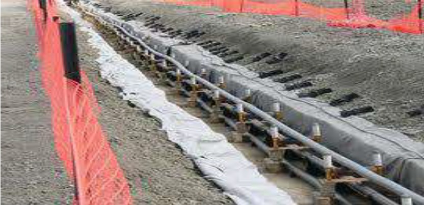
LAYING CABLES IN CONDUIT OR PIPES
• Diameter of Cable Conduit or Pipes : 1.5 x D.
• Cable Entry & Exit – Bell Mouth or Padding.
• Bending Radii of Steel or Plastic Ducts : > 1.5m.
• Single Core Cables Not To Be Laid In Steel Ducts.
LAYING CABLES IN LONG DUCTS
• Lubrication : Lead End / Serving / Outer Sheath at Entry Point.
• Petroleum Jelly / Graphite Powder : Reduces Pulling Force by 40%.
• Vertical Distance Between Two Racks : >0.3m.
• Distance Between Wall & First Cable : >25mm.
• Width of the Rack ≤ 0.75m.
• Steel Work Cable Racks / Trays.
• Painted Coat Of Primer + Anti-corrosive Paint.
• Distance Between Two Vertical Clamps ≤ 2m.
LAYING INSIDE A TUNNEL
• Un-ventilated Tunnel – Heat Through The Walls.
• De-Rating Factor : Δ T = W / 3P
where,
Δ T : Increase In Temperature Over Ambient, ˚C.
W : Total Heat Dissipation per meter Length of all
the Cables, W.
P : Perimeter of Tunnel Cross-section, m.
• Tunnel Height ≤ 2 M
• Free Passage of atleast 60 to 80cm.
• Either on Both Side Or in the Middle.
• Due Considerations :
1) Adequate : Ventilation, Lighting, Drainage.
2) Proper Barriers : Isolation of Sections to Contain Flooding & Fire.
3) Building / Structures : Structural Elements / Trenches Under Floor Ducts or Tunnels.
LAYING AND INSTALLATION:
SINGLE CORE CABLES
• Spacing Between Cables ≤ D.
• Cables On Duct Or Racks : Non-magnetic & Non-corrosive Clamps 0.5 – 0.8m.
• Trefoil Improves The Current Distribution & Reduces Sheath Losses
• Binders Spaced 0.5 to 0.6m.
• Not to Installed Individually In Protective Steel Ducts – All Three
Phases In One Single Duct.
LAYING ARRANGEMENT IN FLAT FORMATION

LAYING ARRANGEMENT IN TREFOIL FORMATION
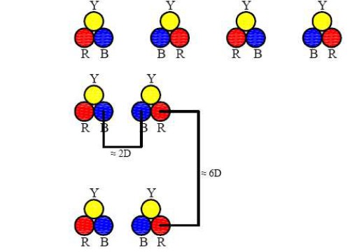
TUNNELING OR HEADING
• A Tunnel Or Heading Under A Roadway Is Preferred To Avoid Opening Up The Road Surface.
• To Lay Number Of Cables – Tunnel Is Preferred.
• To Lay Pipes Or Stoneware Conduits.
• Back Filling Of Excavated Soil.
• Ramming Of Soil To Avoid Road Surface Cracking.
• Tunneling – At Nights & Illumination Of Site.
TRENCHING
• Manual Excavation.
• Excavation With Mechanical Force.
• Thrust Bore.
• Trench Plough.
TUNNELING OR HEADING
• A Tunnel Or Heading Under A Roadway is Preferred to Avoid Opening Up The Road Surface.
• To Lay Number Of Cables – Tunnel is Preferred.
• To Lay Pipes Or Stoneware Conduits.
• Back Filling Of Excavated Soil.
• Ramming Of Soil To Avoid Road Surface Cracking.
• Tunneling – At Nights & Illumination Of Site.
LAYING
• By Hand
Paying Out From A Trailer – Very Slow.
Drum Mounted On A Spindle With Jacks At Either Ends.
Straight And Bend Rollers – 3 to 4m.
Cable Trench Cleaned & Bedded with River Sand.
The Gang-man Standing :
Signaling / Communication To Stop Or Proceed.
Flag – Raising : Pull
Lowering : Hold
Rollers – Graphite Grease.
CURVED ROLLERS

PULLING BY WINCHES
• Cable Subjected To Tensile Stresses.
• Very Sturdy Guide Rollers And Bend Rollers.
• Pulling Armoured Cables – Factory Made Eye
Tensile Forces Checked By Pulling Rope Meter Or Dynamometer
• Cable Entry :
Plastic Or Concrete Ducts :
Boiled Down Soap With A Low Alkali Content.
Steel Ducts : Grease.
PVC Pipes : Graphite Powder.
MAXIMUM PULLING FORCE
• Maximum Permissible Tensile Strength For Cables
For Cables Pulled With Stocking :
PVC & XLPE Armoured Power Cables P = 9 x D²
PVC & XLPE Un-Armoured Power Cables P = 5 x D²
where, P : Pulling Force in N.
D : Outer Diameter of Cables in mm.
For Cables Pulled By Pulling Eye :
Aluminium Conductor : 30 N/mm².
Copper Conductor : 50 N/mm².
CABLE SYSTEM
• Cable Laid :
in Cable Trench.
in Cable Tunnel.
in Pipes.
in Road Crossing.
• Structure.
• Installation Of Joint And Terminations.
PRE COMMISSIONING TEST ON CABLES
FIELD TESTS
1. Installation Test : After the cable laying with/without accessories
(joints/terminations). To detect any manufacturing, transport &
installation damage.
2. Pre-commissioning Tests: (after Laying Test)
Performed after the installation : To detect installation damage in
both the cable and cable accessories.
Significance
• To check the Healthiness of the Cable Insulation.
• Improper Cable Sealing : Water Entry.
EHV CABLES.
• IEC 60840 for cables rated above 30 kV (Um = 36kV) up-to 150kV (Um = 170kV).
• IEC 62067 for cables rated above 150 kV(Um = 170kV up-to 500kV (Um = 550kV).
• IEC 60840. The latest standard calls for only application of AC high voltage test.
• HV DC Test for XLPE Cable – Deleted in the latest standard IEC 62067& IEC 60840 Only AC High Voltage Test.
DC VOLTAGE TEST OF OUTER SHEATH
• A DC Voltage 8kV/mm of specified nominal thickness of the extruded over sheath for 1 minute between the metal sheath & conducting layer.
• Max. Voltage of 25kV DC.
AC VOLTAGE TEST FOR INSULATION
(IEC 60840 & IEC 62067)
• AC Test Voltage :
Subject to agreement between the purchaser and the contractor. The waveform shall be substantially sinusoidal and the frequency : 20Hz and 300Hz. A voltage according to Table 1 shall be applied for 1 hr. Alternatively, a Voltage U0 for 24hrs.
AC VOLTAGE TEST FOR INSULATION
(IEC 60840 & IEC 62067)

TYPICAL PRE-COMMISSIONING TEST CONDUCTED AT SITE
After :
Laying Of Cables.
Preparation Of Joints And Terminations.
110kV Circuits.
66kV Circuits.
Tests :
1. Conductor Resistance Test.
2. Metallic Sheath Resistance.
3. Capacitance Measurement.
1. CONDUCTOR RESISTANCE TEST
After Laying & Installation – Accessories
CR : As per the Conductor Size, Material & Route Length.
By calculating the conductor resistance per unit length from the measured CR
No. of Joints – I²R
R – Joint Resistance of Ferrule/Lug.
Type of Crimping : Effective.
New Technique : Shearing Technique.
2. METALLIC SHEATH RESISTANCE
MEASUREMENT
Conductor Resistance Measurement – Effectiveness of metallic sheath
resistance.
Calculation of Resistance:
Cross-sectional area of the lead sheath/metallic sheath.
ID & OD / Wall Thickness.
Type of material.
Conductivity material.
Checks : Plumbing (@ Joints)
Cable Manufacturer : General Technical Particulars (GTP) specification.
Specified values per unit length.
3. CAPACITANCE MEASUREMENT
The Capacitance Value :
Voltage Rating.
Conductor Size.
Wall Thickness of Insulation.
The Manufacturer’s Cable GTP : Specified values of the capacitance per
unit length.
TECHNICAL CHALLENGES
The Requirements for EHV Cables :
Pre-commissioning Tests.
High Voltage Test.
Total Cable Circuit Length.
Total Capacitance Values :
Very High Voltage Source Rating.
High Transformer kVA Rating at Site.
Practically NOT Feasible.
HIGH VOLTAGE AC TEST SYSTEM
Mobile Test System :
On-site Cable Commission Test set for AC Voltage Tests
Frequency : 20 to 300 Hz
Series Resonant Test System.
Field Testing :
As per IEC 62067 : Test Voltage shall be, 1.7U0 for 1Hr. OR U0 for 24Hrs.
AC VOLTAGE TEST FOR INSTALLATION (IEC 62067)
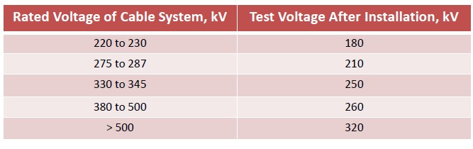
FIELD TESTING
OFC – 300mm², 220kV
Operating Pressure : 2.0kg/cm²
Alarm Lower Limit : 1.8 kg/cm²
Alarm Higher Limit : 4.6 kg/cm²
RESULTS :
IR 300 GΩ
Tan δ @ 50Hz & @ 10kV : 0.0021
(Max permissible value 0.003)
Dielectric Spectroscopy @0.1 Hz : 0.00210
Tan δ @ 50Hz : 0.0024
OBSERVATIONS
For a healthy OFC Cables – Tan δ Values are same both at 0.1Hz & 50Hz.
Tan δ Measured at 50Hz & 2kV to 10kV in steps of 2kV – Flat Response.
Though Cable Rating 220kV – Tan δ at 50Hz.
U0 : 127kV – Realistic figure (at approximately 10% stress level).
This Technique adopted for checking healthiness of OFC Cables.
PREQUALIFICATION TESTS ON EHV CABLES
EHV Cables And Accessories
• Backbone Of Transmission System.
• Higher Electrical Stress.
• Higher Wall Thickness Of Insulation : Greater Thermo-mechanical Effects.
• Design & Co-ordination.
• Reliability : Highest Priority.
• The Pre-qualification Test shall comprise the Electrical Tests on the Complete Cable System with Approx. 100m of Full Sized Cable including atleast
One of Each Type of Accessories.
PREQUALIFICATION TESTS ON
EHV CABLES
The Normal Sequence of Tests shall be as follows :
a) Heating Cycle Voltage Test.
b) Lightning Impulse Voltage Test On Cable Sample.
c) Examination of the Cable System after completion of the Tests.
• The Pre-qualification Test may be Omitted if an Alternative Long Term Test has been carried out & satisfactory service experience can be demonstrated.
IMPORTANCE OF PREQUALIFICATION TESTS
Term Qualification : Synonymous to Type Test.
Pre-qualification :
Long Term Accelerated Ageing Test.
Pre-qualification Performed : Final Stage of Development Process.
IMPORTANCE OF PREQUALIFICATION TESTS
Cigre Study Committee 21 Set Up aWorking Group 21.03.
Recommended the New Standard should Cover Cables up-to 500kV Level also.
Cigre Advised Long Term Accelerated Ageing Test known as “Prequalification Test”.
IEC 62067 – 2001 Cover the Test Methods & Requirements for Power Cables with Extruded Insulation & their Accessories for Rated Voltages above 150kV up-to 500kV.
RANGE & EVIDENCE OF PREQUALIFICATION TESTS
When a Pre-qualification Test has been successfully performed on a Cable System :
• It qualifies the Manufacturer as a Supplier.
• It is recommended to Carry-out Test Using a Cable of a Large Crosssection.
• A Test Certificate Issued by an Independent Test Laboratory shall be Acceptable as Evidence of Pre-qualification Testing.
HEATING CYCLE VOLTAGE TEST
• Application of Voltage & Current through the Conductor.
• Conductor Temp. 0˚C to 5˚C above the maximum conductor temperature in normal operation.
• The Heating shall be applied for at-least 8Hrs. The Conductor Temperature shall be maintained within the stated temperature limits for at-least 2Hrs. of each of Heating Period. This shall be followed by at-least 16Hrs. of Normal Cooling.
• A Voltage of 1.7U0 & Heating Cycles shall be applied to the assembly during the whole of the Test Period of 8760Hrs. (1Yr : 24 x 365).
• Practical Limitation of Test Source : 1.5U0 for 2Yrs. (Cigre Report).
• The Cycles of Heating & Cooling shall be Carried-out at-least 180 Times.
• No Breakdown shall Occur.
LIGHTING IMPULSE VOLTAGE TEST
• Min. total active length of 30m Or alternatively test on the whole test assembly.
• Cable Conductor Temperature 0˚C to 5˚C above the max. Conductor Temperature in normal operation.
• The Impulse Voltages shall be applied according to the procedure as given in IEC 60230.
• The Cable Samples shall withstand failure 10 Positive & 10 Negative Voltage Impulses of the Appropriate Values. Philosophy of AC & Impulse Test :
• AC Test followed by Impulse Test.
• Impulse Test followed by AC Test.
VISUAL EXAMINATION
• Examination Of The Cable System :
a) Cable And Accessories.
b) Unaided Vision.
c) NO Signs of Deterioration (e.g. Electrical Deterioration, Moisture Ingress, Leakage, Corrosion Or Harmful Shrinkage).
d) Adversely Affects The System In Service.
PRECAUTIONS
• Cable : Quality Control – Manufacture.
• Laying : Service Condition, Types of Soil, Paralleling of Cables, Cable in Duct.
• Accessories : Joints & Terminations.
• Skill : Trained Jointer.
• Material : Should be good compatible to the cable under use.
• Crimping : The most important point in jointing.
• Pre-commissioning Test.
• Diagnostic Tests.
• Regular Maintenance.
Silane Cross linked Cables V/s Dry Cure Cables - A Comparison
XLPE Cable manufacture upto 33Kv Sioplas Vs CV Line
- A number of processes have been advocated for manufacture of HT XLPE cables by different manufacturers. Let us compare the best-known methods of steam and gas curing viz-a-viz Sioplas Technology. First, we explain the basic manufacturing process involved in HT XLPE cables with their merits and de-merits.
- Plain Polyethylene has a liner molecular structure and therefore has a lower heat resistance. Due to the excellent electrical properties, polythylene was always the most preferred insulating material for power cables. However, the enhance the thermal characteristics of natural polyethylene, crosslinking was developed by Dow Corning, where by linear structure of PE is converted into a three dimensional linked matrix.
- Three methods for crosslinking polythylene have been developed. One is cross-linking by irradiation, second is chemical crosslinking using peroxides and the third and the latest method is silane process.
- Crosslinking by irradiation has limitations as the irradiated energy gets attenuated as insulation thickness increases. Chemical crosslinking by peroxides is an extensively used practice where insulated core are vulcanized in long heating tubes. Silane grafting is the latest technology where crosslinking is enhanced by grafting siloxane bonds into polyethylene. Let us look into the various aspects of this process.
Extrusion is carried out in true triple head system and the line is fully automatic. After extrusion the curing is carried out in hot water thereby the rate of crosslinking process is slow. This eliminates chances of over-curing or brittleness of insulation and avoids formation of bundled linking locations. The cross-linked ma is quite uniform and therefore the electrical characteristics of PE is kept intact and the thermal properties are enhanced. Silane process has the following advantages.
1. Nil void formation: The gradient is heat transfer right after extrusion and cooling is very less and the curing process is comparatively slow. This eliminates the chances of void formation in insulation.
2. Homogenous Insulation: The extrusion is carried out in true triple head and therefore the conductor screen, insulation and insulation screen are processed simultaneously. This ensures proper bonding of screens to insulation and protrusions/voids in screen interfaces are eliminated. The insulating and screening materials are fed directly from the compound boxes using automatic feeders which eliminates chances of contamination.
3. Nil Diescorching: There is no heating tube involved and therefore there is no possibility for shooting up of die temperature. Hence die scorching in the process is nil.
4. Easy processing: The long lengthy heating tubes used in conventional curing methods are eliminated. This enables easy process monitoring and control. The cables manufactured under this process have excellent electro-mechanical characteristics. These cables have very high di-electric strength, higher impulse voltage with standability, very low di-electric losses and better operating temperatures.
The general feeling in lndia amongst the users of HT cables, is that both steam curing and hot curing results in development of micro voids. Whereas the fact is that use of high pressure steam to cross link polyethylene leads to micro voids within the insulation. When polyethylene is in contact with steam at relatively high pressure and temperature moisture is absorbed at high concentration so that on subsequent cooling super saturation of the water in the polyethylene takes place. Thus, in turn leads to condensing of the water into discreet droplets in the insulation. After natural dissipation of the water from cross link polyethylene the vacant droplet sites becomes micro voids. While micro voids are far too small to cause electric discharge at normal power cable stresses, there is a reduction in the intrinsic electrical strength due to their presence. This is disadvantages when HT cables are required to operate at high electric field stresses. Thus at enhance stresses polyethylene cross link by pressurized steam technique may be unsuitable. To avoid the above, modification to curing process were carried out and the steam was replaced by Nitrogen gas at high pressure and temperature. This avoided the micro void and retained the di-electric strength.
Lot of research and studies have been carried out world over to compare the two most popular techniques of Sioplas and gas curing. The results of various test conducted are highlighted below which confirms that for cables operating upto 33KV with operating stresses upto 4KV per mm both above processes have shown that there is adequate margin of safety both in A.C. & impulse strength
Sioplas by similar reasoning has got similar di-electric properties as that of dry cured XLPE cable. The agency for cross linking in sioplas is moisture and not high-pressure steam which leads to micro voids. By virtue of this future sioplas is more suitable for high voltage insulation over steam cured XLPE.
In fact, Sioplas technique offers all the advantages of dry cure XLPE but without the complexity. The influence of water on the silane cross link insulation turned out to be very small in comparison to the curing done by chemical methods. This makes the silane cross link insulation more reliable for longer use.

In silane cross linking curing take place in a aqueous environment because the water is needed in the insulation to achieve the cross linking. Nevertheless,
the cross link take place at moderate temperature and at atmospheric pressure.
The binding of the polyethylene molecules in a peroxide cross linking insulation is a linear one. This means that at one binding site, two polyethylene molecules are attached together. In case of silane cross linking the binding is a three dimensional one. At one binding site, an average of four molecules are attached together. It is a known fact that three dimensional structure is more stronger than the linear one. Also as time passes by cross linking multiplies and the bonds become more and more stronger.
Since void formation is practically nil, chances of formation of electrical trees like bow tie trees and vented trees in insulation after prolonged service is very remote.
Treeing Effect: The subject of water treeing in polymeric insulations isa subject of much research & discussions. It is certain that the presence of moisture is a necessary condition for water tree growth. It is clear that when electrical stresses are applied to the insulation, water trees grow from the water containing micro voids.
It has been shown that the only way to prevent growth of water trees is by complete absence of water. AII cross linkable techniques include contact with water or steam for curing on cooling & even those methods which do not use water as a processing medium, the polyethylene contains water produced from the decomposition of the cross linking peroxide.
Experiments were carried out on dry cured cables and cables with sioplas technique for following tests:

It was observed that breakdown distribution of the silane cross link insulation both in respect of mean value and the spread in breakdown strength is at par with more well known peroxide process.
The breakdown strength of insulation in case of peroxide cross linking decreases substantially whereas in case of silane cross linking it does not.
The national (IS 7098-2: 2011) or international standards (IEC 60502-2 : 2014, BS 6622: 2007, BS 7835: 2007, DIN VDE 0276-620: 2018, SANS 1411-4: 2009 etc.) specify the properties to be achieved by the XLPE compound in the finished cable. All the standards are silent on the method to achieve it.
If we compare the properties – we find that requirements of the properties are identical. Parameters from few standards are shared as follows;
a) Properties from IS 7098-2
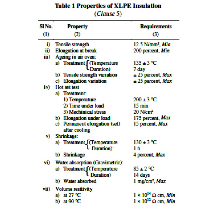
b) Properties from IEC 60502-2


c) Properties from SANS 1411-4
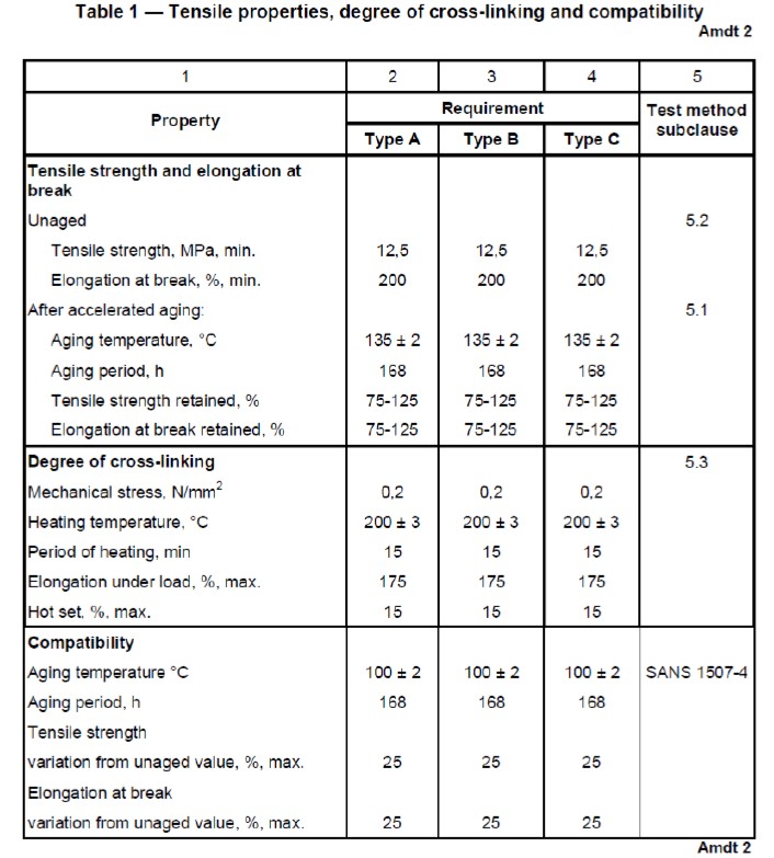
d) Properties from SANS 1411-4
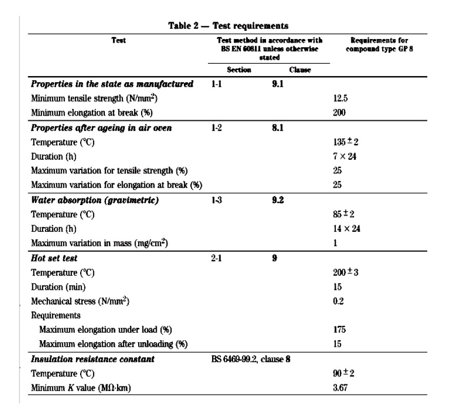
Hence the results of test prove that upto 33kv grade, silane process can be used safely as a alternate to gas cured technique. The cables produced with the silane process are with quality which is as good as that produced with gas cured technique. Both A.C. breakdown strength as well as the discharge magnitude fulfill the severest of demands. The effect of water on silane cross link insulation is surprisingly small.
More over as explained above, there is no differentiation between the test methods or test results of dry cure as well as silane cross linked cables. Since the cross linking does not stop in the tube, but continues even in usage, this makes the silane cross linked cables upto 33 kv more reliable for longer use. In this respect silane cross linking is well comparable to that of dry curing.
Moreover, after the cable is manufactured there is no test which will conclusively prove or route through which the cable is cured.
Also, the silane cross link polyethylene insulated cables have been in operation since early 1980s and have shown excellent performance in service.
The DC electrical performance of sioplas XLPE cables is superior to that of Nitrogen peroxide cured cables.
The long-term AC electrical performance of sioplas XLPE cables is equivalent to that of Nitrogen peroxide cured cables.
Development of new enhanced tree retardant sioplas material has shown to further improve the long-term AC electrical performance.
(Sources: AEI Cables, U.K., CPRI papers & letters, High Voltage Research Laboratory, Netherlands)
Moisture Management systems in Power Transformers – A need of the hour
Introduction
Power and distribution transformers are the most important and expensive assets in an electrical power network. Compared to other equipments, they are very reliable and require very little maintenance since they have no continuous moving parts. However, the insulating paper material, being organic will degrade with time, and thereby cause damage to the transformer.
Water is a by-product of the decomposition of the long chain hydro-carbon glucose molecules of cellulose that makes up the paper and pressboard insulation. Excessive moisture will saturate the insulation and increase its conductivity.
At higher temperatures vapour or free moisture can develop increasing the high risk of partial discharge and flash-over faults. Moisture has a great influence on the life expectancy and the load carrying capacity of a transformer. Moisture reduces the electrical and mechanical strength of the solid insulation. In general, the
mechanical life of the insulation is halved for each doubling of the ppm water content; the rate of thermal deterioration of the paper is directly proportional to its water content.
The design life of power transformers is usually 30 to 35 years. In fact the typical Time to Failure of a large generator transformer (working at constant full load) is 18 to 24 years and a transmission or distribution transformer (working at half load or less) can be 40 to 60 years. The actual life of a transformer is determined by ageing of the cellulosic insulation in the form of paper on conductors and leads, and of pressboard used for inter-turn or intersection spacers. The insulation life is determined by three factors:
• Operating temperature
• Access to oxygen
• Water absorbed in the paper.
As cellulose ages the length of the glucose chain slowly reduces due to chain schism from 1200 molecules to about 200 molecules when it no longer has sufficient mechanical strength to be viable.
Operating temperature
- Unless redundancy has been built into the transformer rating at the specification stage, a transformer is always likely to operate at or near the rated value. For every 6.5º C increase in operating temperature the insulation life will halve, based on moisture content in the paper of 0.3% by weight.
- The remnant life of the transformer will be reduced whenever it is operating at high temperature. The rate of ageing will be higher (up to 50 times faster at moisture contents of 5% in the paper), and the remnant life will be much reduced.
Oxygen
Ageing is due to chemical reactions between the long-chain glucose molecule of cellulose and oxygen. With no oxygen present there can be no ageing of the paper, but oxygen is always present either as air dissolved in the oil or as water in the oil or paper. Attempts to replace air in the oil by nitrogen or an electro-negative gas have always failed, but a rubber-based membrane has been used with success to prevent direct contact between the oil and the atmosphere. Unfortunately the material of the membrane has a lifetime of only 10 to 15 years before is begins to allow air and water vapour to diffuse through it. In addition, water at up to 10% of the weight of cellulose is formed by the chemical process of ageing. Fitting a membrane will trap water formed during this process and moisture is locked into the system where it is a catalyst causing more
rapid ageing of the insulation.
Water
Under normal conditions oil will dissolve 60 ppm water before it saturates. Cellulose saturates at 10% water content when it is dry and between 12 and 18% water content when it is oil-impregnated. The presence of moisture as a contamination in the oil-paper insulation system will compromise the dielectric strength of the paper and will act as a catalyst for rapid ageing of the insulation system. Moisture can enter the oil-paper system in several ways:
• It can remain absorbed in the insulation if the factory drying process has been inadequate.
• It can enter the transformer during service if the air drying system has not been properly maintained, diffuse through gasket material or enter through cracks in the tank (welding defects).
• It can enter through openings in the tank if the internal insulation has not been correctly protected during site erection operations or during service outages.
• In addition, water is generated internally in the transformer as the paper and pressboard materials age in service. The rate of ageing in service is accelerated by operation at high temperature, by the presence of oxygen as air dissolved in the oil or as water in the paper.
Mitigation to reduce ageing
- The traditional means of protecting the insulation system of a transformer from the ingress of water is to fit a silica gel breather. These breathers need to be maintained as often as every two weeks and do not remove moisture generated inside the transformer by ageing of the insulation.
- Refrigerated breathers based on Peltier devices are widely used to continuously remove water from oil in the conservator. These devices will slowly remove water from the cellulose insulation but are ineffective when water in the paper exceeds 2.5% by weight.
- Oil filtration plant based on heat and vacuum operations are effective in drying the oil, but as more than 99% of the moisture is absorbed in the paper, it quickly migrates into the oil and the oil remains wet.
- Molecular sieve drying devices are connected to circulate the main tank oil over a charge of molecular sieve material; this is a naturally occurring zeolite selected with a 4 Angstrom pore size to match the size of a water molecule. Water is trapped at up to 40% by weight of molecular sieve material through chemical
bonding, and can only be removed by a heat and vacuum process to break the energy bonds holding water in the material. Molecular sieve drying devices can be used to slowly remove moisture from the cellulose insulation by removing water from the oil. The movement of water from cellulose to oil takes place at the same rate as the movement of water from oil into the molecular sieve material. High levels of moisture have been removed from the insulation of transformers over a period of weeks and months to reduce the risk of the transformers failing due to electrical surges or through mechanical faults associated with high through-fault
currents. - An alternative water management scenario is to fit molecular sieve devices to new transformers, in combination with refrigerated breathers or diaphragm seals. The molecular sieve device absorbs water dissolved in the oil and removes water produced by degradation of the cellulose as it is formed. This combination of devices is effective in maintaining high integrity of the transformer insulation by eliminating the main catalyst for ageing and avoiding a reduction in the dielectric performance of the insulation structure.
TRANSx is an on-line molecular sieve, manufactured by Ravin Group.
- TRANSx will continuously remove water from the oil and from the paper insulation in a power transformer while it is fully operational. This on-line process not only reduces ageing, but will improve the dielectric strength of the oil, and increase reliability. Plumbed into the oil ‘circuit’ of a transformer, the circulation pump will pump the oil across the molecular bed, which, through chemical bond, will attract water particles contained within the oil. By constantly reducing the level of water contained within the oil, water contained within the solid insulation, where over 95% of the water is trapped, will migrate into the oil to maintain the natural water equilibrium. In this way water gradually moves from the solid insulation, to the oil, and then trapped by the molecular sieve.
- A 10 micron particulate filter will at the same time remove extraneous matter, such as fibres, which can become ionised, being attracted to areas of high electrical stress and causing a flashover. TRANSX is designed to be a slow, non-invasive, gradual process, that will by lowering the ppm level of water in the oil, encourage water to migrate from the solid insulation to maintain the natural hydrostatic equilibrium, and hence over a period of time, significantly reduce the water contained within the solid insulation, and therefore reduce the rate of ageing, extending the life of the transformer.
- The TRANSx system has the capacity to remove approximately 10 litres of water from a transformer before saturation, but the rate at which it will adsorb water will depend on many factors, mainly, how much water is available in the oil, and the temperature range through which the transformer will operate. The design flow rate of the pumped oil is nominally 90 litres per hour to give maximum adsorbtion through the molecular bed. The oil temperature does not have to be elevated to give optimum adsorbtion. A single TRANSx cylinder will adsorb approximately 30% of the weight of the zeolite material giving a theoretical volume of 3.9 litres. of water. The rate at which this adsorbtion takes place is dependant on availability of water, temperature, and the % saturation of the cylinders, the process will slow as total saturation is reached. The Isostere graph shows that the adsorbtion performance of the zeolite improves with a reduction of temperature, whereas other dry out devices require elevated temperature to allow effective dry-out. However, we know that the higher the temperature of the transformer, the faster the rate of ageing of the paper insulation material. Typically a CL3AM on a wet (insulation water content 4% by dry weight) hot transformer operating in a hot humid ambient climate might saturate in 6 to 9 months.
- A CL3AM on a dry (insulation water content 1% by dry weight) operating at 50° C might take 24 months to saturate. A CL3AM on a brand new transformer (insulation water content 0.3% by dry weight) might take 5 years before saturation. No specific claims for ppm levels in oil are made by TRANSX, as the reduction of ppm will always depend on the ‘wetness’ of the transformer, and the dynamic operating conditions. The product is judged on the amount of water that is removed, which is reported to the client when the cylinders are replaced and regenerated.
Possible figures to support text
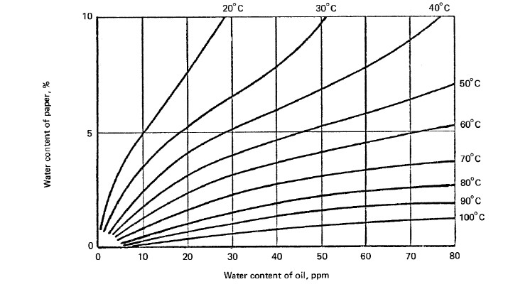
REGENERATION
When the cylinders are found to be saturated they must be replaced. TRANSX (UK) offers a cylinder exchange where we supply three previously ‘regenerated cylinders’ for either the client, or TRANSX to fit in place of the existing ones. This is done by simply using the quick fit couplers on the top and bottom of each
cylinder, and removing each cylinder in turn. The couplers self seal, so there is no oil loss. The three replacement cylinders are then fitted and the quick couplers snapped shut. At the same time the particulate filter should also be changed. The ‘wet’ cylinders removed are then returned to TRANSX ( India), who will
carry out the regeneration process. Method statement TR003 must be observed for the cylinder change process. (available on request)
MATERIALS & PERFORMANCE SPECIFICATION
ADSORBTION MATERIALS & PERFORMANCE:
Zeolite – Crystalline Aluminoscilicate with binders (CAS-No. 1318-02-1; EINES-No 215-283-8)
3 Anstrom bead size. Non-flammable and bio-degradable.
Weight of beads per cylinder – 13 kgs
Oil Volume per cylinder – 12 litres
Oil Type – New un-inhibited napthynic to IEC 60296 (3)
Adsorbtion capacity of water per cylinder – Maximum 30% of bead weight (3.5 litres – approx 10 to 11 litres total
for 3 cylinders per cycle)
MATERIALS IN CONSTRUCTION:
Cylinders: 304 grade stainless steel all welded construction with quick fit couplers for ease of removal.
Frame: 304 grade stainless steel all welded construction.
Pump: Caned Rotor sealed circulation pump running at average 90l/hr -25ºC to 110ºC
Pipework: 15mm x 1mm wall Stainless Steel seamless tube with all welded joint construction
wherever possible.
FITTINGS: Stainless Steel ¼ turn ball valves, flow indicator, de-aerator, non return valves
etc. Lockable air bleed valve, accessible at ground level on 6mm diam. copper– up
to 5 m capillary tube Non- return valve, ½” BSP, brass body construction.
MONITORS: Vaisala MMT 162 probes at input and output for SCADA signal for oil temperature
and ppm water in oil, with local LCD display.
LEM monitor for incoming LV supply and pump integrity.
INSTALLATION Typically for CL3AM mounted on transformer:
MATERIALS: 2 x 1.5m length of 15mm stainless steel pipe
2 x Flange Adaptors – 15mm pipe to take off valve flange size.
4 x ½” BSP M x 15mm SS male stud couplings.
3 x ½” BSP M SS hex nipples
TYPE TESTING: Random unit selected for test once every 12 months.
System pressurised to 3 bar for 1 hour at 110ºC (pump not running) to prove leak free.
ROUTINE TEST: Every production unit.
Each individual cylinder is tested under 4 bar pressure prior to TRANSx unit assembly
Each unit is tested pressurised to 2 bar for 30 minutes at 60ºC to prove leak free.
EHV CABLE LAYING PROCESS & RECOMMENDATIONS
Installation of EHV Cables
This paper elaborates on the various methods of cable laying and the advantages and disadvantages of the same. The common way of cable laying: buried method, tunnel method, cable trench method, pipe laying method, vertical shaft method, hangers and bridge method and so on.
DIRECT BURIAL
Cable route shall be selected to avoid excess bending portions and to keep them as few as possible. It is recommended that the bending radius at corners should be maintained at least a few times the minimum bending radius, preferably more than 5 metres, as larger radius provides lower side wall pressure. Enough space shall be maintained inside the cable trench. Furthermore, it shall be confirmed from available records of existing services and utilities as well as with sufficient number of trial holes along the trench route, especially at joint bay locations, that the trench route has no obstructions. It shall also be confirmed that no chemical agents, that could be harmful to the cables, are present in the surrounding soil and water along the route. Always use a cable pulling winch. When pulling cable mechanically by the pulling winch, the cabling winch rope is coupled to the cable by means of the pulling eye. The pulling tension is thus transferred to the conductor. Pulling tension should not exceed the maximum permissible pulling tension recommended by Ravin in their technical data.

CABLE DUCT SYSTEM
Larger bending radius is generally required in duct systems as compared to direct buried cable. Since coefficient of friction of ducts is larger than that of cable rollers used in direct burial installation, resulting in higher pulling tensions, consequently the maximum section lengths between joint bays is relatively shorter than that for direct burial.
Therefore, each section length should be determined after careful calculation of the pulling tension and the sidewall pressure of the corresponding section. Cable expansion from duct due to thermal expansion should also be considered when dimensions of joint bays are determined. Offset arrangements should be envisaged to absorb the thermal behaviour of the cable during its service life. For a single cable in a duct, the inner diameter of the duct should be greater than at least two times the outer diameter of the cable being pulled. Internal surface of the duct including the surface at joints shall be smooth and free from any defects such as protrusions, projections, cracks, scratches, sharp edges etc., which may cause damage to cable outer sheath during pulling. Any sharp edges at
both ends of the duct should be rounded off and pipe collars provided at ends. The PVC pipe collar should be installed at both ends of the ducts so as to prevent the duct edges from damage. Immediately prior to the installation of the cable, the ducts shall be thoroughly cleaned using conduit cleaning devices to ensure that any small pebbles, sand or other foreign material is removed before cable is installed. Use mandrels with a diameter 6 mm less than the duct size to check for breaks or sharp edges in the duct that would damage the cable. On completion of inspection, put the guide rope by blowing in to the pipe and connect to the winch pulling rope. Each duct should be provided with a draw wire and both ends of the duct should be plugged in a proper manner to prevent ingress of any foreign material like soil, sand, concrete, water etc. Only winch pulling shall be applied for cable duct installation. The cabling winch rope is coupled to the cable by means of pulling eye. The pulling tension is thus transferred to the conductor. The pulling tension should not exceed the maximum permissible pulling tension recommended by Ravin in their technical data.
Lubrications of Cable
The use of cable lubricants, as the cables are pulled into ducts lessens the cable tensions and prevents any scratching of cable jackets due to irregularities in ducts. A liberal use of lubricant is recommended for all pulling operations. Only lubricants that are compatible with the outer sheath material (PVC, HDPE, and/or MDPE) shall be used. Petroleum-based lubricant shall never be used for any formation with polyethylene jackets. The lubricant is usually applied to the cable as the cable enters the duct or the feeding tube.
CABLE TUNNEL
Cable tunnel dimensions shall be so designed as to secure enough space both for settling of cables on supporting structures and for installation and jointing works. The bending corners of the cable tunnel should also be designed to provide the permissible bending radius to the cable with enough margins. When cables are laid on cable racks or cable supports, they shall then be fixed with cable cleats or clamps at adequate intervals to absorb the thermal expansion and contraction with their lateral or vertical movement within the length between adjacent cleats. If cables are laid without any binding, they may move according to the thermal behaviour and may drop from the rack or supports. Further, the metal sheath of the cable may be subjected to excessive strain at bent portions where the thermal movement of the cable is partially concentrated. In order to avoid this movement, snake installation i.e. laying the cable in uniform waveform, is usually applied along the route on racks or supports, to encourage the absorption of the cable movement smoothly. At the end of the cable route, the cable ends should be set straight and fixed with cable clamps before rising to the sealing ends.
SPECIAL CONSTRUCTION
There may be many types of special constructions along the cable routes, such as river crossings, road crossings, cable tunnel and cable bridges. Special care must be taken to lay cables at such locations. It is not possible to list all counter measures to cope with and cover every special construction; however, following are generally recognised as the basic key points that should be taken into account:
a) The thermal environment must be satisfactory.
b) Any thermo-mechanical forces that could be experienced must be adequately constrained or dissipated.
c) Where cables are exposed to air, care must be duly taken of risks due to fire, vandalism, accidental damage by third party. Cables must also be provided adequate protection against direct solar radiation.
d) Exposure to vibration.
e) Specified bending radius must be observed.
CABLE LAYING
Most adequate method should be adopted to pull the cable considering site conditions, so as to avoid any damage to the cable due to excessive mechanical forces experienced during cable installation and to ensure an efficient installation. It must be ensured that the cable to be installed can be pulled without any damage or defect in terms of cable pulling design according to route drawings and site conditions. Preliminary study shall be made to determine proper cable laying method, direction of cable pull, arrangement of tools/equipment, communication equipment, manpower and other necessary factors in order to achieve satisfactory cable installation. The most effective method of pulling a high voltage cable is by nose pulling with a cable pulling eye fixed to the conductor.
CABLE PULLING DESIGN
In order not to damage the cable during pulling, it is recommended to pull the cable keeping both the pulling tension and the sidewall pressure lesser than the permissible figures.
DATA OF CABLE REQUIRED
Following data on the cable is required for cable pulling:
a) Overall cable diameter (mm)
b) Cross sectional area of conductor (mm2)
c) Unit weight of cable (kg/m)
d) Material of conductor (copper / aluminium)
PERMISSIBLE VALUES
Permissible maximum value of pulling tension, which depends on the method of pulling, is decided by the criteria as detailed under or that as recommended by Ravin:
Fmax = A. dmax
A = Conductor cross sectional are (mm2)
dmax = Maximum permissible stress (N/mm2)
= 50 N/mm2 for single core Copper Conductor
= 30 N/mm2 for single core Aluminium Conductor
Maximum Cable Pulling Tensions will be followed as per below table:
MAX. CABLE PULLING TENSIONS FOR HV CABLES

XLPE insulated HV cables = 5000 N
Cable laying/pulling on rollers = 1500 N
Cable laying/pulling through plastic pipes = 7500 N
COEFFICIENT OF FRICTION
Following are the coefficient of friction between the cable outer sheathing and the rubbing surface during laying
process.
• Pulling cables over rollers : μ = 0.15 – 0.3
• Pulling cables through concrete ducts : μ = 0.4 – 0.6
• Pulling cables through concrete ducts:
– Grease Lubrication: μ = 0.15 – 0.25
– Water Lubrication: μ = 0.15 – 0.25
– Grease and Water Lubrication: μ = 0.10 – 0.20
If cables are to be pulled through long plastic pipes, it is essential that a lubricant be used. Otherwise, the heating produced as a result of friction between the cable and the plastic surface could cause the thermoplastic sheathing to stick to pipe walls.
MINIMUM TEMPERATURES FOR CABLE LAYING
High Voltage Cable should not be laid at temperatures below -2°C.
In case, the cable must be laid at temperatures below -2°C, the cable must then be heated in special insulated
tents at 30°C – 40°C for 24 hours and then must be laid rapidly.
CABLE PULLING FORCE CALCULATIONS
a) Horizontal/Flat Cable Pulling
The pulling force (F) at the end of the cable path is given by:F = W.I.μ
Where: W = Cable weight (kg/m)
I = Length of cable route / path (m)
μ = Coefficient of friction
b) Sloping Cable Path Pulling
The pulling force (F) will be increased when laying sloping up/uphill and decreased when laying sloping
down/downhill and is given by:
F = WI (μ cos b ± sin b)
Where: b = angle of slope
+ is used for uphill laying
– is used for downhill laying
On slopes up to approximately 20 deg. (36%), the pulling force may be calculated by:
F = (W.I.μ) ± (W.h)
Where:
h = difference in level (mm)
c) Curved Cable Path
When the cable is pulled around a curve, the pulling force is increased by a factor (f), which is dependent on the coefficient of friction (μ) and the angle of the bend (μ)
Fo = Fi x eμμ = Fi x f
Fo = Force at exit of bend
Fi = Force at entry of bend
μ = Coefficient of friction
μ = Bend angle in radians
f = eμμ, factor from table
Table for Value of f (eμμ=f):
Bend Angle μ= 0.1 μ= 0.15 μ= 0.2
Degrees Radians (on new roller)
CABLE LAYING WORK
General Instructions:
This section describes general instructions to be observed during cable pulling work.
a) Handling of Cable
At the time of acceptance and prior to installation, the cable reel should be thoroughly examined for any outside damage or damage to cable end caps. This examination should also include lagging, reel flanges and reel marking, tags and labels. While handling cables, necessary precaution should be taken to prevent damage to the cables.
Cable reels that are to be transported on trucks must be securely blocked or anchored to prevent rolling. If a reel of cable is to be rolled for any appreciable distance, it shall be rolled in the direction indicated by the arrow on the reel flange or with the outside end of cable trailing, if not marked, so as not to loosen the turns of cable on the reel. When rolling reels on the ground, they shall be carefully eased over any rough surfaces. Care shall be taken to avoid damaging reel lagging in order that outer layer of cable remains protected. In removing lagging from cable reels, care shall be taken not to damage the cable. Remove all nails, staples or bolts from inside flange before unreeling cable. Care is to be taken to prevent cable from dragging.
Before Cable Pulling
It shall be confirmed that trench floor or other places where the cable is to be installed are free from any foreign materials such as stones, nails and pieces of concrete, asphalt, brick pieces, glass pieces, sharp-edged objects etc., which may damage the cable. Such materials should be removed at least 30 cm away from the trench. Any water inside the trench should be pumped out completely. The trench wall must be secured appropriately in accordance with specification prescribed by the client. The cable trench curves must be checked thoroughly, to ensure that the minimum bending radius of the cable is attained. Sweet sand (or backfill soil as required by project specifications) shall be evenly distributed on the trench floor with minimum thickness of 150 mm or to a thickness prescribed in
the project specifications.
Prior to start of cable pulling, Ravin recommends to conduct the DC sheath test on the reel in order to ensure that no damage has taken place during transporting and handling of the cable. Upon completion of the test heat shrinkable end caps, to protect against ingress of water or foreign particles, must immediately seal the exposed area. Whenever a cable is cut, the exposed end shall be sealed to protect from rain, mist or dripping or splashed water by heat shrinkable caps. The drum should be mounted on transport and laying trailer. For cable pulling, the cable drum shall be set at the opposite direction to the arrow painted on the drum that indicates the direction of rolling during transportation. Care should be taken not to damage the cable by battens when removing them from the cable drum. The direction of pulling should be so chosen so as to require the least pulling strength at the end of the cable path.
3) Reliable communication between the drum, the head of the cable, on curves, entrance to duct, intermediate post and the winch has to be established to effectively coordinate the work process. The equipment to be used should be of proven reliability and should be thoroughly tested before cable installation begins. Ensure that the winch has a pulling recorder and a tension meter, to continuously monitor the cable pulling force. It should not exceed the maximum pulling force of the cable recommended by Ravin.
4) Essential words or signals for cable pulling, at least START and STOP, are fixed and understood by all the associated staffs. The meeting prior to cable pulling is recommended to decide position of watchmen with communicative equipment to guide cable pulling works. Watchmen shall be positioned every 50 metres and at every corner.
5) It shall be confirmed that cable drum, drum brake, winch, rollers, wire rope, drum for wire rope and any other necessary tools/equipment have been set properly. Swivel shall be installed between wire rope and pulling eye to prevent the cable from twisting. At the entrance to the cable trench, a cable guiding and bearer stand is positioned, over which the cable taken off the cable drum is pulled into the trench. The rollers that are inclined towards the centre ensure that the cable is fed centrally into the trench. The rule for curves in the trench is that under no circumstances should they fall below the minimum prescribed bending radius of the cable (15 x ØD of cable). The cable rollers in straight portions shall be set at approximately 2 metre intervals to avoid the slack of the cable pulling. Whereas the cable rollers in bend portions shall be set as close as possible, so as not to be subjected to the sidewall pressures partially. Sufficient numbers of corner cable rollers are positioned on the curves in the trench, to prevent cable sliding off. In field practice anchor pins have proved ideal for anchoring the corner rollers.
6) Final check of trench shall be carried out so as to eliminate the risks that may damage the cable. And it shall be confirmed that trench will not collapse at any portion along the cable route. Timbering/Shuttering shall be provided securely prior to cable pulling at positions where trench may or is liable to collapse. 7) When the cable is pulled into shaft or inclined tunnel, sufficient capacity of brake facilities shall be applied so that the cable may not slip down due to its weight.
7) When the cable is pulled into shaft or inclined tunnel, sufficient capacity of brake facilities shall be applied so that the cable may not slip down due to its weight.
During Cable Pulling
where the smooth pulling may be blocked. After confirming that no damage has occurred at these portions, the
pulling tension may be increased. Necessary action should be taken to eliminate the cause of damages, in case of
its occurrence.
2) Watch the cable on the cable rollers, especially at bend portions and maintain sufficient clearance between
existing services and the cable along the whole cable route all the time during cable pulling.
3) The pulling tension and the sidewall pressure should never exceed the permissible values. It is essential to be
able to control the speed of pulling by monitoring pulling force speed and the length.
These parameters should be recorded continuously on a recorder, which is an indication and proof of the correct
laying. When pulling force exceeds the maximum permissible setting, the pulling should stop.
4) The outlook of the cable shall be checked and it shall be confirmed that the cable has not been damaged during
cable pulling. The cable pulling should be stopped immediately on finding any damage and should not be resumed
until the causes are removed. The damage portion of cable shall be repaired as required.
5) When the inner end of the cable on the cable drum is loosened during cable pulling, it shall be tightened again
to the cable drum.
After Cable Pulling
1) The outlook of the cable shall be checked whether the cable has been damaged or not. Any damage shall be repaired in a proper manner after careful examination.
2) Integrity of anti-corrosive sheath shall be confirmed by carrying out DC high voltage test on it before and after backfilling. Immediately after the first phase of backfilling and prior to final backfilling, DC sheath test at 10 kV for 1 minute should be conducted to ensure that no damage has occurred to the cable sheath during cable pulling. Upon completion of the test heat shrinkable end caps to protect against ingress of water or any foreign particles, must immediately seal the exposed area.
3) Necessary protection to the cable shall be provided against mechanical damage, vandalism and any other possibility to damage the cable. It is recommended to backfill the trench as soon as possible and not to leave the cable exposed.
4) The cable end shall be raised up higher than the maximum water level expected. The integrity of sealing at the cable ends shall be confirmed to prevent water or any moisture entering the cable. Repair work shall be carried out if necessary.
5) Power cables and auxiliary cables shall be arranged so as to keep the specified distance between them, in order to maintain the current rating capacity and to limit sheath current/sheath induced voltage of the cable and induced voltage on auxiliary cables as per designed values.
Ravin Group supplies and installs high voltage cables and systems on turnkey packages. We provide our customers with a comprehensive cable service package which encompasses system design, design and selection of cables and compatible accessories, supply of quality materials, installation, testing, commissioning and finally ensuring full safety and reliability of the installation.
Our installation team consists of a highly qualified and experienced team of engineers, who work with clients and manufacturers to identify the quickest and most cost effective power solutions. Our team has been trained and experienced in various countries around the world, and they carry with them over 250 years of cumulative experience in specialty jobs. We have an experience of installation of more than 150 kms of EHV cables and 300 joints and terminations at voltages greater than or equal to 220 kV.
We provide our customers with a comprehensive cable service package which encompasses system design including design and selection of cables and compatible accessories, supply of quality materials, installation, testing, commissioning and finally ensuring full safety and reliability of the installation.
The Necessity of EHV in Urban Transmission
The Necessity of EHV in Urban Transmission
The energy market has changed dramatically over the last years as a consequence of deregulation, privatisation and unbundling of generation and transmission. The new network owners mainly focus on the cost-effectiveness of their assets. This applies to new network investments but, certainly, also includes the optimisation of usage of the existing underground network. The design of a High Voltage underground system is extremely important and requires an in-depth knowledge of cables, accessories, methods of installation, the fault current of the system and impact on the electrical network. In the world of today, the EHV systems are basically EPC contracted, and need to specialize in providing total management of major projects and offer a complete turnkey approach, from system planning to final testing and post-sale services. Installation design and methods, co-ordination and scheduling of installation activities, are as crucial as the manufacture of cables and accessories to achieve a reliable and satisfactory connection. It is necessary to operate to the highest accreditation and safety standards to meet the demands of the most complex project environments. Turnkey approach, worldwide experience, top class customers references and strong focus on innovation represent the winning recipe that makes Ravin the world leader in HV systems. The effective management of the existing networks requires different knowledge and experience, as they are often of hybrid nature (fluid filled, gas insulated and XLPE extruded cables).
As India marches towards the 21st Century, power becomes an essential ingredient for infrastructural development. With rapid urbanisation around the corner to sustain the industrial growth, the necessity of transmitting large blocks of power to load centres assumes significance. Over the years, there has been a marked increase in the voltage level for transmission of bulk power, due to the distinct advantages offered by the use of high voltage.
Necessity for EHV Transmission: With increase in transmission voltage, for the same amount of power to be transmitted, the current in the line decreases which reduces I2R losses. This will lead to increase in transmission efficiency. With decrease in transmission current, size of conductor required reduces which decreases the size of conductor. The transmission capacity is proportional to square of operating voltages. Thus the transmission capacity of line increases with increase in voltage. With increase in level of transmission voltage, the installation cost of the transmission per km decreases. It is economical with EHV transmission to interconnect the power systems on a large scale. The number of circuits and the land requirement for transmission decreases with the use of higher transmission voltages. Over the years, there has been a marked increase in the voltage level for transmission of bulk power, due to the distinct advantages offered by the use of high voltage. This had ushered in the generation of Extra High Voltage (EHV) power transmission systems with voltage grades of 66 kV and above. This is something which we will call the Power of “Urban Transmission”.
Underground EHV cables are also used for evacuating bulk power generated in pumped storage hydroelectric power generating stations, situated at a lower altitude, at outdoor switchyard located at a higher altitude. Similarly, underground cable systems are the appropriate means of power transmission over short distances where erection of overhead tower lines would be infeasible considering the space constraints. It is in this context that Cross-linked Polyethylene (XLPE) insulated cables offer significant advantages.
As an insulating material, XLPE combines the advantages of improved mechanical and thermal properties with excellent electrical characteristics of high dielectric strength, low relative permittivity and low di-electric losses . These advantages have rendered what XLPE cables can achieve today – carrying large currents at voltages up to 500 kV, with an inherent higher short circuit withstand capacity of 250oC. Additional benefits that accrue are simple construction, easy installation and trouble-free operation.
EHV cables come in different combinations as per the features mentioned in chart below:
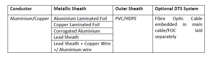
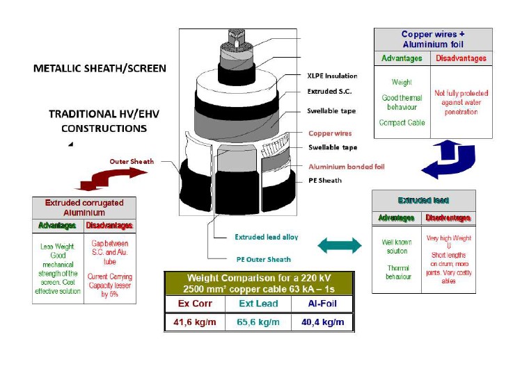
EHV Cable Design
The 3 fundamental components of an EHV cable:
(1) Conductor
(2) Insulation System (Conductor screen, Insulation and insulation screen)
(3) Metallic Screen/Sheath Complex
(1) DESIGN OF THE CONDUCTOR
The 2 basic Design drivers for designing the conductor are:
(a) Current Rating (continuous operation and short circuit)
(b) Mechanical Behaviour (flexibility, pulling strength)
Current Rating depends on:
– DC resistance: choice of metal and cross section area (CSA) CSA = depends on maximum DC resistance (IEC 60228) or minimum weight (US standards)
– AC resistance: depends on choice of construction (stranded/segmented) and wire surface treatment (bare/oxidised/enamelled)
Additional features:
• Longitudinal water blocking system
• Semi-conducting binder
(2) DESIGN OF THE INSULATION SYSTEM
The 2 basic Design drivers for designing the insulation system are:
(a) Electrical Gradients
(b) Thermo-Mechanical & Thermo-Electrical Properties
(a) Electrical Gradients depend on:
– Intrinsic reliability Life curve and reliability derivation
– Qualification coverage Type test and prequalification coverage (IEC 60840, IEC 62067, Cigré Technical Brochure
303)
(a) Thermo-Mechanical & Thermo-Electrical Properties:
– Dissipative Power Factor (tg δ)
– Dielectrical losses = f (U²)
– Relative permittivity (ε)
Reactive power (power flows); charging current (off load current, setting of protections)
– Temperature withstand
In continuous operation, in overload and short circuit
(3) DESIGN OF SCREEN / SHEATH COMPLEX
The 2 basic Design drivers are:
(a) Mechanical Properties
(b) Thermo-Electrical Properties
(a)Mechanical Properties:
– Bending capability (laying behaviour)
– Core protection (shocks, punctures, radial water tightness)
– Fatigue (thermal cyclic loading)
(b)Thermo-Electrical Properties:
– Short circuit capability (IEC 60949, IEC 61443, Cigré TB 272)
–Screen losses (generated in AC systems)
Additional features:
• Longitudinal water blocking system
• Outer sheath
– Anti-corrosion protection
– Safety of personnel (induced voltages)
– Mechanical strength (abrasion during laying, deformation in cleats)
– Special properties:
• Flame retardancy & LSOH
• Anti-termite / anti-rodent properties
• UV protection
• Resistance to hydrocarbons and solvents
Anatomy of an EHV Cable
Normally, high voltage cables are characterised by the presence of the following components:
• Conductor
• Semi-conducting conductor screen
• Insulation (also called “dielectric”)
• Semi-conducting insulation screen
• Metallic sheath or screen
• Protective outer covering
Each of these components is described in the following paragraphs:
Cable Components
CONDUCTORS
Conductors are made from copper or aluminium, using wires or segments. Copper conductors are mainly used when a high current carrying requirement is needed (typically >1000 A) in addition to higher fault current. In case of lower requirements, aluminium conductors are frequently preferred due to the lower cost impact. Another important parameter that has to be taken into account is the resistance with alternating current. Because of the skin effect, the “a.c. resistance” of a conductor tends to be more significant as the cross section increases. The skin effect forces the current to flow along the peripheral areas, so the central section of the conductor becomes less efficient. For this reason, a special conductor construction, called “segmental Milliken”, is used with big cross sections (from 1000 up to 2500 mm2). The conductor is typically divided in 5 or 6 segments that are slightly

insulated from each other, so the current is “constrained” to flow inside the segments.
Figure 1: A 400 kV cable with a Milliken conductor
Moreover, in order to obtain a further reduction of the skin effect, it’s possible to oxidise or enamel a certain percentage of the wires inside the segments. The 400 kV cable shown in Figure 1 has a Milliken conductor.
Water blocking of the conductor is generally recommended in order to limit the water propagation along the conductor in case of damage to the cable. Insulation and semi-conducting screens
The main materials used for high voltage extruded cables are detailed below:
a) High Density Polyethylene (HDPE) is a thermoplastic material that was used for a limited period. Due to its limitations with regard to its working and short circuit temperatures (respectively 80°C and 150°C), HDPE insulation has been replaced by other extruded materials. HDPE has also been observed to have some difficulties in handling the cables at low temperatures.
b) Ethylene Propylene Rubber (EPR) is a thermosetting compound and it is made from a blend of components, which formulation can be modified in order to obtain specific characteristics. It is manufactured and offers good performance in terms of “water treeing” resistance, as well as good elasticity characteristics. EPR has high dielectric losses compared to XLPE and this has limited its use to the maximum voltage level of 150 kV. EPR has a rated maximum conductor
temperature of 90°C, an emergency rating of approx 130°C and a conductor short-circuit rating of 250°C.
c) Cross Linked Polyethylene (XLPE) is a thermosetting material. It offers a degree of purity higher than that offered by the EPR and this makes this insulation a suitable material for applications up to 500 kV. Contrary to EPR insulation, XLPE is very sensitive to moisture which would lead to its degradation. For this reason, it’s necessary to prevent water penetration into the insulated core. This is achieved by applying a radial water barrier. XLPE cables have rated maximum conductor temperature of 90°C and an emergency rating of up to approx 105°C (depending on emergency time). The conductor short-circuit rating is 250°C.
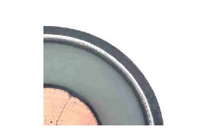
Figure 3: A Close-up of an extruded XLPE cable
Figure 3 shows a close-up of an XLPE cable and the black semi-conducting screens can be seen on each side of the XLPE insulation. Semi-conducting screens are used on all high voltage cables from 6.6 kV onwards to ensure a smooth electrical interface between conducting and insulating regions. The stranded profile of the conductor would initiate localised field concentration (i.e. high stress areas) if interfaced directly with the insulation and a consequent risk of ionisation and ultimately electrical breakdown. Hence, provision of semi-conducting screens removes these high stress areas and provides uniform stressing at the interface with the insulation.
To ensure a good interface, all three layers (i.e. conductor screen, insulation and insulation screen) are extruded in one process (triple extrusion). The electrical properties for the various extruded type insulations are detailed below:

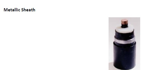
Figure 4: A lead sheathed XLPE cable
While EPR cables up to 150 kV may be used without any metallic barrier, it is recommended that all XLPE cables with rated voltages higher than 60 kV are provided with a radial moisture barrier comprising one of the following metallic sheaths:
• Extruded lead sheath
• Extruded corrugated aluminium sheath (CAS)
• Smooth longitudinally welded aluminium sheath (WAS)
• Aluminium or copper laminated and glued foil
The main functions of the metallic sheaths are:
• Protection against the ingress of moisture
• To give mechanical protection, thus preventing damages against external actions
• To withstand the single-phase fault current
• To carry the charging current
• To provide the earth or near-earth potential reference for the cable insulation ometimes the above designs may be used in combination with copper wires or aluminium wires in order to increase the short circuit carrying capability.
All the above sheathing methods have advantages and disadvantages when compared towards the following topics:
• Thermal performance
• Electrical performance
• Corrosion resistance
• Water resistance
• Mechanical fatigue
• Weight
• Environmental impact
Consideration of the optimum sheathing system will usually depend on the specific application and maybe also any specific country requirements.
Outer Sheath
Generally PE (polyethylene) is used as the sheathing material for buried cables. This is normally medium-density polyethylene (MDPE) or alternatively high density polyethylene (HDPE), both of which provide good mechanical protection, good corrosion protection and good resistance to abrasion. PVC (polyvinyl chloride) may also be used for buried cables. Cables laid in air (gallery, shaft, tunnel, etc.) normally have either a flame retardant PE or a PVC sheath. Both systems are widely used.
Manufacturing process of HV XLPE Cable

EHV Cable Accessories Installation of EHV Cables and Accessories Ravin Group supplies and instals high voltage cables and systems on turnkey packages. We provide our customers with a comprehensive cable service package which encompasses system design, design and selection of cables and compatible accessories, supply of quality materials, installation, testing, commissioning and finally ensuring full safety and reliability of the installation.
Our installation team consists of a highly qualified and experienced team of engineers, who work with clients and manufacturers to identify the quickest and most cost effective power solutions. Our team has been trained and experienced in various countries around the world, and they carry with them over 250 years of cumulative experience in specialty jobs. We have an experience of installation of more than 150 kms of EHV cables and 1500 joints and terminations above 66 kv and 300 joints and terminations at voltages greater than or equal to 220 kV.

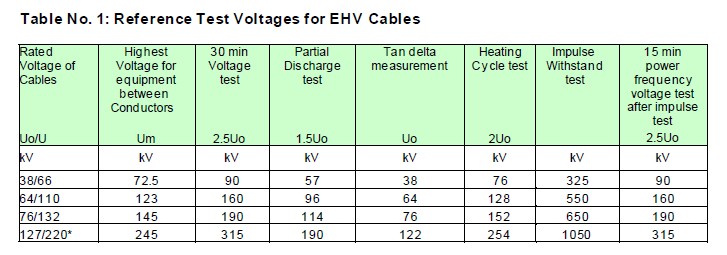
More resources
Reference Documents
Useful information including gland sizing charts, BS7671 Wiring Regs tables, and Good Practice Guides.
Cable training and CPD learning
Access our product ‘cheat sheets’ for handy overviews and learn about our CPD courses for more in-depth learning.

Cable Calculator
Use our quick, simple tool for sizing low voltage cables against British and International standards.